
LVT-120 · Lesson 11 of 12 · 19 min
Design rules, limits and cable counts
The previous lessons set out the parts of a structured cabling system and the rules for each. Design is the work of putting them together for a real building: deciding how many outlets go where, where the telecommunications rooms must be, how much cable each room serves, how big the pathways must be and, finally, how much material to order. On Cobalt Line's projects this is Sanjay's work, but every technician should understand it, because the field is where a design meets the building, and a technician who knows why a design looks the way it does can spot the problems it did not anticipate. This lesson gathers the design rules into one place and walks through the calculations, ending with the cable takeoff and bill of materials that turn a drawing into an order.
The rules in one place
Most design checks come back to a short list of numbers. Sanjay keeps them on one page at the front of every design file.
| Rule | Value | Source |
|---|---|---|
| Horizontal cable, panel to outlet | 90 m (295 ft) maximum | TIA-568.1 |
| Channel, equipment to equipment | 100 m (328 ft) maximum, 10 m of cords | TIA-568.1 |
| Work area cord | 5 m (16 ft) recommended maximum | TIA-568.1 |
| Consolidation point | at least 15 m (49 ft) from the room; up to 12 work areas | TIA-568.1 |
| Connections in a channel | up to four | TIA-568.1 |
| Backbone cross-connect levels | no more than two | TIA-568.1 |
| Telecommunications rooms | at least one per floor; more for large areas or long routes | TIA-569 |
| Conduit between pull points | 100 ft, two 90 degree bends | TIA-569 |
| Conduit fill, three or more cables | 40 percent | Code tables, TIA-569 |
| J-hook spacing | 5 ft maximum | TIA-569 |
| Work area planning figure | one per 100 ft², at least two outlets | TIA-568.1 |
| PoE bundles | 24 cables or fewer recommended | TIA TSB-184-A |
From requirements to outlets
Design starts with the owner's requirements and the architect's floor plans. Sanjay goes through the plans room by room and places outlets: the work area outlets from the owner's standard or the planning figure, the device outlets for every access point, camera, card reader, display and controller shown on the other trades' drawings, and the outlets the owner asks for in particular rooms. He then adds a grid of wireless access point locations, roughly every 60 ft in open areas and adjusted to the walls and ceiling heights, because wireless coverage is now the most demanding requirement in most buildings. Each outlet is a horizontal cable, and on current projects device outlets are a growing share of the total, in some buildings a third or more.
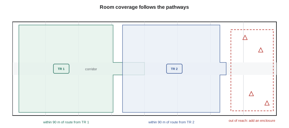
Every outlet location is then checked against the telecommunications rooms. Sanjay draws, on the floor plan, the area that each room can reach within 90 m of cable route. Because routes follow corridors and ceilings, that area is not a circle but an irregular shape, shrinking around obstacles. Any outlet outside every room's area needs a new room or enclosure, a different route or, for a device far away, a fiber-fed enclosure near it.
With the outlets placed, the counts follow: cables per room, panels and ports per room, switch ports, backbone strands, and then pathway sizes for each corridor and branch, using the fill rules of Lesson 9. Spare capacity is planned at each level. Sanjay typically leaves about 20 percent spare ports on patch panels, rack space for growth as in Lesson 3, and room in pathways for future cable, as the owner's standard requires.
Power over Ethernet and cable bundles
When a cable carries Power over Ethernet, some of the power is lost as heat in its conductors. A single cable warms only slightly, but in a large bundle the inner cables cannot shed their heat, and the bundle's temperature rises. Higher temperature raises insertion loss, as Lesson 5 showed, and can approach the temperature rating of the cable jacket. TIA's guidance, TSB-184-A, addresses this for PoE currents of up to about 1,000 mA per pair, which covers the 90 W level of IEEE 802.3bt Type 4. It recommends Category 6A or better cable for new PoE installations, avoiding bundling where possible and limiting bundles to 24 cables where they cannot be avoided, and it notes that larger conductors and shielded cables run cooler.
The heat in one cable can be estimated from Ohm's law. With power on all four pairs, current flows out on two pairs and back on the other two, with the two conductors of each pair sharing the current. The resistance of each conductor and the current through it give the power lost.
# Heat produced in one PoE cable (illustrative; current per powered pair set)
r_per = 2.0               # one 23 AWG conductor, ohm per 100 ft at 20 C
length = 295              # ft
per_pair_ma = {"802.3af (15.4 W)": 350, "802.3at (30 W)": 600,
               "802.3bt Type 3 (60 W)": 600, "802.3bt Type 4 (90 W)": 960}
r_cond = r_per * length / 100
for name, ma in per_pair_ma.items():
    i_cond = ma / 1000 / 2            # each conductor carries half the pair current
    pairs = 2 if "af" in name or "at" in name else 4
    conductors = pairs * 2
    loss = conductors * i_cond ** 2 * r_cond
print(f"{name:24} {pairs} pairs powered, {ma} mA per pair set: {loss:5.2f} W lost in the cable")802.3af (15.4 W) 2 pairs powered, 350 mA per pair set: 0.72 W lost in the cable 802.3at (30 W) 2 pairs powered, 600 mA per pair set: 2.12 W lost in the cable 802.3bt Type 3 (60 W) 4 pairs powered, 600 mA per pair set: 4.25 W lost in the cable 802.3bt Type 4 (90 W) 4 pairs powered, 960 mA per pair set: 10.87 W lost in the cable
The figures run from under a watt per cable at the lowest PoE level to about ten watts at the highest. That sounds small, but a bundle of 48 cables at the Type 4 level puts several hundred watts, the output of a small space heater, into a bundle a few centimeters across, spread along its whole length. That is why designs that serve many high-power devices, such as an office lit by PoE luminaires or a wall of PoE displays, spread their cables across more pathways, use smaller bundles in open tray rather than tight ones, and avoid routing them through hot spaces.
The cable takeoff
A takeoff is the measurement of material from the drawings. For horizontal cable, the usual method is to measure the route to every outlet from its telecommunications room, add the allowances of Lesson 5 for the rack, the wall drop and the service loops, and sum. On a large job with hundreds of outlets, estimators often use the average-length method instead: measure the routes to the nearest and farthest outlets served by a room, take their average, add the allowances, and multiply by the number of cables. The method works well when outlets are spread evenly across the area a room serves, and Sanjay checks it against a few measured routes before he trusts it.
Horizontal cable is sold in boxes or reels, most commonly 1,000 ft. A box cannot be used to its last meter, because each pull uses whole cable lengths, and the end of a box is usually shorter than the next cable. The number of full cables that can be pulled from one box is the box length divided by the cable length, rounded down, and the boxes needed is the number of cables divided by that, rounded up. Pulling several cables at once, as is normal, means pulling from several boxes at once, so a crew pulling a bundle of six cables needs six boxes open.
# Cable takeoff and bill of materials for one telecommunications room
import math
shortest, longest = 46, 270          # measured routes, ft
allowance = 30                       # rack, wall drop and service loops, ft
cables = 212                           # horizontal cables in this room
box = 1000                             # ft per box
waste = 0.10

average = (shortest + longest) / 2 + allowance
per_box = math.floor(box / average)
boxes = math.ceil(cables / per_box)
total = cables * average * (1 + waste)
print(f"average cable length {average:.1f} ft, {per_box} cables per box, {boxes} boxes")
print(f"cable for budget with {waste:.0%} waste: {total:,.0f} ft")
bom = {"Category 6A outlet jacks": cables,          # panel ports are built into the panels
       "48-port patch panels": math.ceil(cables / 48 * 1.2),
       "faceplates (average 2.5 ports)": math.ceil(cables / 2.5),
       "labels (two per cable, faceplate and port)": cables * 4,
       "equipment cords": cables}
for item, n in bom.items():
print(f" {item:42} {n:5d}")average cable length 188.0 ft, 5 cables per box, 43 boxes cable for budget with 10% waste: 43,842 ft Category 6A outlet jacks 212 48-port patch panels 6 faceplates (average 2.5 ports) 85 labels (two per cable, faceplate and port) 848 equipment cords 212
Each item in the list is checked against the design. The panel count includes the 20 percent spare ports. The faceplate count depends on the mix of single and multiple outlets, and Sanjay counts faceplates from the outlet schedule rather than from an average when the schedule is ready. Equipment cords are often supplied by the owner, and the specification says who provides them.
Checking a design in the field
Designs are drawn on plans that do not always match the building. Walls move, ducts take the space reserved for tray, ceilings are lower than drawn and outlets are relocated by the tenant. Technicians are the first to see these changes, and Cobalt Line asks them to report anything that affects a design rule: a route that will now exceed 90 m, a pathway that will be overfilled, a room that has lost space, an access point location that has moved behind a new wall. Dev's practice is simple: measure, compare with the design, and raise anything that crosses a rule with Sanjay before the cable is pulled, not after it fails its test.
Worked problem
A long route at the Hartwell warehouse office
At the Hartwell warehouse, the office area's new design places a training room at the end of the office wing. Maya measures the route from the office telecommunications room to the training room's farthest outlet during rough-in: 243 ft along the tray and hooks, plus a 10 ft wall drop, 10 ft at the rack and a 10 ft service loop, through a ceiling that reaches about 95 °F in summer. Is the route acceptable?
Show solution
- Total cable length: 243 + 10 + 10 + 10 = 273 ft.
- Temperature reduction for unshielded cable: 95 °F is 15 Celsius degrees above the 68 °F reference, and 15 × 0.4 percent = 6 percent, so the allowance becomes about 277 ft.
- The route is within the reduced allowance, by less than 4 ft, with no room for a detour or a longer service loop.
- Maya reports the margin to Sanjay, who decides to keep the route but specify shielded cable for that room's links, which is affected less by temperature, and to tell the installers not to add slack.
Answer: The route passes with almost no margin; the designer adjusts the cable type rather than adding a new room for one space.
Designing for the next twenty years
The last design question is always what the building will need in the future. Sanjay asks owners how long they expect to occupy the space, how often they reorganize and what they expect to add: more access points as wireless standards advance, more cameras, PoE lighting, building sensors. He then decides where to spend on spare capacity now, usually pathways, rack space and backbone strands, which are expensive to add later, and where to wait, usually extra horizontal cables in areas whose use is uncertain. A design that leaves room to grow is cheaper over the building's life than one that fits today's needs exactly.
Common mistakes
MistakePlacing outlets without checking route length to a room.
InsteadCheck every outlet against the 90 m route reach of its room.
MistakeIgnoring device outlets in the count.
InsteadCount access points, cameras, readers and controllers; they are a growing share of the cables.
MistakeBundling large numbers of high-power PoE cables tightly.
InsteadUse smaller bundles, Category 6A or better, and spread cables across pathways.
MistakeUsing the average-length method on an uneven layout.
InsteadCheck it against measured routes, or measure every route.
MistakeOrdering cable as total length divided by box length.
InsteadCount whole cables per box; the end of each box is waste.
Summary and key terms
- Design gathers a small set of rules: 90 m and 100 m, four connections, two backbone levels, room count, pathway fill and support, work area figures and PoE bundle sizes.
- Outlets are placed from owner requirements, the planning figure and every device on the other trades' drawings, plus a wireless access point grid.
- Each outlet must be within 90 m of route from its room; coverage follows the pathways, not straight lines.
- PoE heats cables; Category 6A and bundles of 24 or fewer cables keep temperatures under control.
- Takeoffs measure routes or use the average-length method, add allowances and count whole cables per box.
- Technicians check designs against the building and report anything that crosses a rule before the cable is pulled.
- Takeoff
- Measurement of material quantities from drawings.
- Average-length method
- Estimating horizontal cable by averaging the shortest and longest routes from a room and multiplying by the number of cables.
- Bill of materials
- The list of materials and quantities needed for a job.
- Coverage area
- The part of a floor that a telecommunications room can reach within the horizontal length limit.
- TSB-184-A
- TIA guidance on cabling for Power over Ethernet, including bundle sizes.
- Spare capacity
- Ports, rack space, pathway room and strands left for growth.
Practice problems
Work each problem on paper first, then reveal the answer to check.
A room's shortest and longest routes are 65 ft and 230 ft, with 30 ft of allowances. What is the average cable length?
Show answer
(65 + 230) / 2 + 30 = 177.5 ft.
How many 177.5 ft cables can be pulled from a 1,000 ft box?
Show answer
1,000 / 177.5 = 5.6, so 5 whole cables.
How many boxes for 150 such cables?
Show answer
150 / 5 = 30 boxes.
What does TSB-184-A recommend for bundle size?
Show answer
No more than 24 cables where bundling cannot be avoided.
Lesson quiz · 5 questions
Score 60% or more to complete this lesson.
Create a free account to save your progress, take quizzes and earn a certificate.