
ELEC-230 · Lesson 6 of 12 · 24 min
Pulling conductors
Once the raceway is installed, the conductors must be pulled into it without damage. On small branch circuits, a fish tape and a careful helper are enough; on large feeders, a pull involves reels weighing hundreds of kilograms, a powered puller, a crew in radio contact and a calculation of the forces on the cable. A damaged conductor may pass inspection and fail years later, so the techniques in this lesson matter long after the job is finished. The lesson covers planning a pull, the tools, conductor identification, estimating pulling tension, lubricants, the pull itself, and testing afterwards.
Planning the pull
Before pulling, confirm that the raceway is complete, clean and correctly sized: every coupling tight, every bushing in place, every end reamed (Lesson 2), and the fill and total bends within the code limits (ELEC-220, Lesson 2). Then decide:
- Which conductors go in each raceway, in what sizes, colors and lengths, from the panel schedules and feeder schedules (Lesson 11). Measure or calculate the run length, then add enough for terminations and a margin.
- The pull direction. Tension builds up through the run, and bends multiply it, so a run with bends near one end is usually pulled so that the bends come early in the pull, where tension is still low: feed the cable in at the end nearest the bends and pull from the far end.
- The equipment: fish tape or blower and line, rope of adequate strength, a hand-pulled or powered puller, sheaves or pulling elbows at pull points, reel stands or a cable cart, lubricant, radios.
- The crew: someone feeding at the reel end, someone at the puller, and people at intermediate pull points, all in communication. Everyone knows the signal to stop.
Tools for pulling
- Fish tapes: steel, fiberglass or nylon tapes pushed through a raceway to pull in a rope or small conductors. Non-conductive tapes are safer near energized equipment.
- Blower and vacuum systems: a vacuum or compressed air pulls or pushes a foam piston (a "mouse") attached to a light line through the raceway, quickly and over long distances. The light line then pulls in a stronger rope.
- Pull rope: low-stretch rope rated well above the expected tension. Stretchy rope stores energy and can whip violently if it breaks.
- Cable pullers (tuggers): capstan-type machines that wind the rope around a rotating drum, controlled by an operator who regulates tension by how hard the rope is held. Larger pullers have tension gauges and automatic limits.
- Basket grips (wire mesh grips) and pulling eyes attach the rope to the conductors; for groups of conductors, the conductor ends are staggered and taped smoothly so the head of the pull passes through fittings without catching.
- Sheaves and pulling elbows guide the cable at pull points and at the raceway entrance, protecting it from sharp edges and reducing friction.
- Reel stands, jacks and spindles let large reels turn freely, so the cable feeds without being dragged or kinked.
Conductor identification
Conductors are identified by color so that each phase, neutral and bonding conductor can be traced. Codes fix some colors: the neutral (identified conductor) must be white or gray, and the bonding or equipment grounding conductor green (or green with yellow stripes, or bare). Phase colors are partly code and partly convention:
In the United States, the NEC requires white or gray for the grounded (neutral) conductor and green, green with yellow stripes or bare for equipment grounding conductors, and requires that the identification method for ungrounded conductors be posted at each panel (210.5(C) and 215.12(C)). By common convention, 208Y/120 V systems use black, red and blue, and 480Y/277 V systems use brown, orange and yellow, with gray neutrals for 277 V.
Large conductors are often available only in black, so they are identified at every termination and accessible point with colored tape or labels. Where several systems share a building, conductors of different systems must be distinguishable, and neutrals of different systems kept separate and identified.
Estimating pulling tension
For long or heavy pulls, estimate the tension before pulling, to choose the equipment and pull direction and to check that the conductors will not be damaged. For a straight section, the tension added is roughly the weight of the cable times the coefficient of friction times the length:
At a bend, the tension leaving the bend is the tension entering it multiplied by an exponential factor that depends on the friction coefficient f and the bend angle θ in radians:
With lubricant, f is typically 0.3 to 0.5; a 90° bend (θ = 1.571 rad) with f = 0.4 multiplies tension by about 1.87. The order of sections matters: tension is multiplied at each bend, so a bend near the end of the pull, where tension is already high, adds much more than the same bend near the start.
Worked problem
Estimating a feeder pull
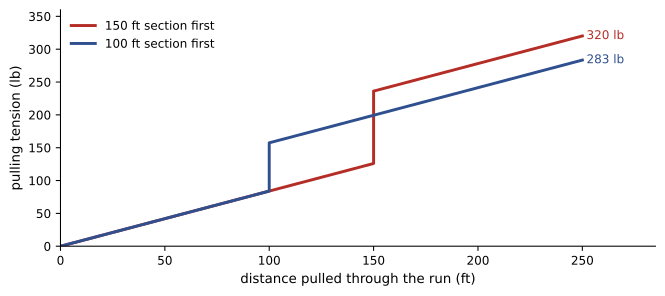
Three 4/0 AWG copper conductors, weighing about 0.7 lb/ft each (2.1 lb/ft for the group), are pulled through a conduit run consisting of 150 ft straight, a 90° bend, then 100 ft straight. Take f = 0.4. Estimate the pulling tension, and compare pulling in the opposite direction.
Show solution
- Direction 1: first straight: 2.1 × 0.4 × 150 = 126 lb. Bend: 126 × 1.87 = 236 lb. Second straight: 236 + 2.1 × 0.4 × 100 = 320 lb.
- Direction 2 (100 ft first): 84 lb; after the bend 84 × 1.87 = 157 lb; then 157 + 126 = 283 lb.
- A common maximum for copper pulled by the conductors is 0.008 lb per circular mil per conductor: 4/0 is 211,600 cmil, so about 1,690 lb each, or about 5,000 lb for three (manufacturers give exact limits).
Answer: Both directions are far below the conductor limit; pulling with the shorter section first gives the lower tension (283 lb). The same method, applied to long runs with several bends, shows when a pull needs an intermediate pull point or a different direction. Sidewall pressure at bends, the force pressing the cable against the inside of the bend, must also stay within the manufacturer's limit for large cables.
Another hazard is jamming. When three conductors of the same size are pulled into a raceway whose inside diameter is about three times the conductor diameter (a ratio between about 2.8 and 3.2), the conductors can wedge side by side in a bend and jam, producing enormous tension. Checking this ratio and choosing a different raceway size avoids the problem.
Lubricants
Pulling lubricants (wire lubes) reduce friction, often halving tension compared with dry pulling. Use a lubricant compatible with the conductor insulation and jacket, as stated by the lubricant and cable manufacturers. Apply it generously to the conductors as they enter the raceway and, for long pulls, pre-lubricate the raceway by pulling a lubricant-soaked swab through it. Clean up spills, because lubricants make floors slippery.
Making the pull
At the feed end, set the reels so that the conductors feed straight into the raceway without crossing or kinking, with a sheave or feeding tube to guide them over the edge. Pull steadily without stopping if possible, because restarting from rest requires more force than continuing (static friction is higher than sliding friction). The person feeding watches for crossovers, insulation damage and reels that bind, and calls a stop immediately if anything looks wrong. At intermediate pull points, helpers guide the cable around the corner and keep it from rubbing on edges. Never exceed the rope's or puller's rating, and stand out of the line of the rope under tension: a broken rope can snap back with dangerous force.
For branch circuits, the same principles apply on a smaller scale: pull from boxes with enough slack, keep conductors from twisting, and leave at least the minimum free conductor length at each box for connections (commonly about 150 mm or 6 inches, with more in large boxes and panels).
After the pull
Leave enough length at each end for routing and termination, cut conductors cleanly, and protect the ends from moisture until they are terminated. Label every conductor at both ends with its circuit or feeder designation. Before energizing, feeders are tested: an insulation resistance test with a megohmmeter between each conductor and ground and between conductors, at a test voltage suited to the insulation rating (for example 1,000 V DC for 600 V cable), confirms that the insulation was not damaged during the pull. Low or unequal readings between phases indicate a problem that must be investigated before the feeder is put in service. Results are recorded for the commissioning documents.
In the United States, insulation resistance testing of feeders is commonly specified in Division 26 sections, often referencing the NETA Acceptance Testing Specifications (ANSI/NETA ATS) for minimum values and procedures.
Pulling in cable tray and long runs
Cable laid in tray is installed differently from cable pulled through conduit. For short runs, cables are simply laid in by hand. For long runs, rollers are placed every few meters along the tray, with sheaves or radius rollers at every bend so that cables do not drag over rungs or bend below their minimum radius. The cable is pulled with a rope and a puller, or by hand with a team spaced along the route, and then lifted off the rollers into its final position, tied and dressed. On very long underground or tunnel runs, intermediate pullers or cable pushers (which grip the cable and drive it forward) share the load so that no section exceeds its tension limit.
Minimum bending radius applies to every cable during pulling and in its final position. Manufacturers state it as a multiple of the cable diameter (for example 8 or 12 times for many power cables, more for shielded medium-voltage cables). Exceeding it, for example by pulling around a sharp edge without a sheave, can damage insulation and shielding in ways that only appear later as failures. Check the radius of every sheave, conduit body and bend the cable will pass through.
Coordination and records
Large pulls are planned with the general contractor and other trades, because they need space for reels and pullers, may block corridors, and sometimes require openings in floors or walls. Record the pull: date, conductors, reel numbers (so cable lots can be traced if a defect appears), measured or estimated tension, lubricant used, and the insulation resistance test results. These records become part of the turnover documents and are invaluable if a feeder fails.
Common mistakes
MistakePulling without checking that bushings and reamed ends are in place.
InsteadInspect the raceway before pulling to protect insulation.
MistakePulling so that bends come at the end of the pull.
InsteadFeed at the end nearest the bends so tension is low when the cable reaches them.
MistakeUsing stretchy rope or standing in line with the rope.
InsteadUse low-stretch rated rope and stand clear of its line.
MistakeIgnoring the jam ratio for three equal conductors.
InsteadAvoid raceway-to-conductor diameter ratios near 3.
MistakeEnergizing a feeder without an insulation resistance test.
InsteadTest with a megohmmeter and record the results first.
Summary and key terms
- Plan conductors, pull direction, equipment and crew before pulling.
- Fish tapes, blowers, rated rope, pullers, grips, sheaves and reel stands make pulls safe and smooth.
- Neutrals are white or gray, bonding conductors green; phase colors follow code and convention.
- Tension adds wfL on straights and multiplies by e^(fθ) at bends; order matters.
- Check conductor tension limits, sidewall pressure and jam ratios on large pulls.
- Lubricate, pull steadily, watch the feed end, and stay out of the rope's line.
- Label conductors and test feeder insulation before energizing.
- Fish tape
- A flexible tape pushed through a raceway to pull in a line or wires.
- Mouse
- A foam piston blown or vacuumed through a raceway to carry a line.
- Capstan puller
- A machine that pulls rope by winding it around a rotating drum.
- Basket grip
- A wire mesh sleeve that grips cable ends for pulling.
- Sheave
- A grooved wheel that guides cable at a change of direction.
- Coefficient of friction
- The ratio of friction force to normal force.
- Sidewall pressure
- The force pressing a cable against the inside of a bend.
- Jam ratio
- The ratio of raceway inside diameter to conductor diameter.
- Pulling lubricant
- A compound that reduces friction during pulling.
- Megohmmeter
- An instrument for measuring insulation resistance at high DC voltage.
Practice problems
Work each problem on paper first, then reveal the answer to check.
Why is a run usually pulled so that the bends come early?
Show answer
Bends multiply tension, so they add less when tension is still low.
What color must the neutral be?
Show answer
White or gray.
What is the tension multiplier for a 90° bend with f = 0.5?
Show answer
e^(0.5 × 1.571) ≈ 2.19.
What tension does 200 ft of cable weighing 1.5 lb/ft add with f = 0.4?
Show answer
1.5 × 0.4 × 200 = 120 lb.
In the example, which direction gives lower tension?
Show answer
Pulling the 100 ft section first, 283 lb.
What is the approximate maximum tension for one 4/0 copper conductor at 0.008 lb/cmil?
Show answer
About 1,690 lb.
What jam ratio range should be avoided for three equal conductors?
Show answer
About 2.8 to 3.2.
Why pull steadily without stopping?
Show answer
Restarting needs more force because static friction exceeds sliding friction.
What test is done on a feeder before energizing?
Show answer
An insulation resistance test with a megohmmeter.
Why must you stand out of the rope's line?
Show answer
A broken rope can snap back violently.
Lesson quiz · 5 questions
Score 60% or more to complete this lesson.
Create a free account to save your progress, take quizzes and earn a certificate.