
ELEC-220 · Lesson 3 of 12 · 35 min
Motor circuits
Motors are the largest category of load in industry and a major one in commercial buildings: pumps, fans, compressors, conveyors, elevators and machine tools. Motor circuits follow their own code rules because motors behave unlike other loads. They draw five to eight times their running current when starting, they can be overloaded mechanically for long periods without drawing a fault-level current, and their nameplate ratings vary between manufacturers. The code therefore separates protection into distinct functions, each sized differently. This lesson covers motor full-load currents, conductor sizing, overload protection, short-circuit and ground-fault protection, feeders for several motors, disconnecting means, control circuits and circuits for variable-frequency drives.
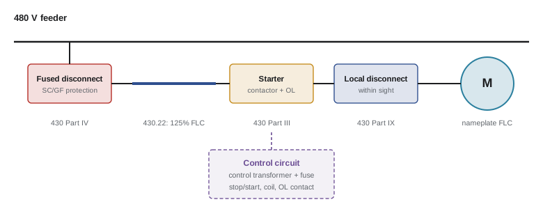
Motor circuits are covered by Article 430 of the NEC, with full-load currents in Tables 430.247 to 430.250 and maximum overcurrent device settings in Table 430.52. Figure 430.1 maps the parts of the article to the parts of a motor circuit.
The parts of a motor circuit
A motor branch circuit has separate elements, each with its own job:
- Branch circuit short-circuit and ground-fault protection (fuses or a circuit breaker): protects the conductors and equipment against short circuits and ground faults, but must be large enough to let the motor start.
- Disconnecting means: allows the motor and controller to be isolated for maintenance.
- Controller (starter or drive): starts and stops the motor.
- Motor overload protection: protects the motor and conductors against sustained overcurrent from mechanical overload or failure to start, usually thermal or electronic overload relays in the starter.
- Branch circuit conductors, sized for continuous duty.
- Control circuit and its protection.
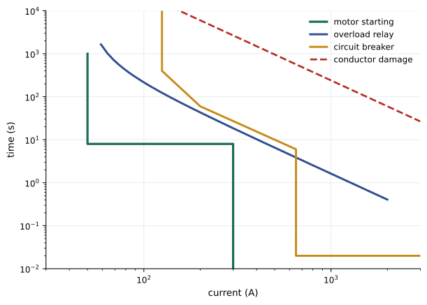
Because the short-circuit device must pass the high starting current, it cannot also protect against overload; the overload relay handles that, and the two are coordinated.
Full-load current: tables or nameplate?
A key principle is which current to use for which purpose:
- For conductors, short-circuit and ground-fault protection and disconnecting means, use the full-load current from Tables 430.247 to 430.250 (430.6(A)(1)), not the nameplate value, so that the circuit will suit any motor of that horsepower that might later be installed.
- For overload protection, use the actual nameplate full-load current (FLA), because overloads protect this particular motor.
| Motor size | Full-load current at 460 V (A) |
|---|---|
| 5 hp | 7.6 |
| 10 hp | 14 |
| 25 hp | 34 |
| 50 hp | 65 |
| 100 hp | 124 |
Branch circuit conductors
Motors may run continuously at full load, and their current varies with load and voltage, so branch circuit conductors for a single motor are sized at 125% of the motor's table full-load current.
430.22 requires conductors supplying a single continuous-duty motor to have an ampacity of not less than 125% of the motor's full-load current from the tables, with Table 430.22(E) giving other percentages for short-time, intermittent, periodic and varying duty.
Worked problem
Conductors for a single motor
Size copper conductors (75 °C terminations) for a 25 hp, 460 V three-phase motor.
Show solution
- Table full-load current: 34 A. Required ampacity: \(1.25 \times 34 = 42.5\) A.
- 8 AWG copper at 75 °C is rated 50 A (Table 310.16); 10 AWG at 35 A is too small.
Answer: 8 AWG copper, before applying any correction factors for ambient temperature or more than three current-carrying conductors. Voltage drop on long runs should also be checked, since starting current causes large momentary drops.
Overload protection
Overload devices, usually thermal or electronic relays in the motor starter, trip when current stays above their setting for long enough, with a time-current characteristic that allows starting current briefly but trips on sustained overload or a locked rotor. They are sized from the nameplate current and the motor's service factor or temperature rise.
430.32 requires overload protection for continuous-duty motors over 1 hp, set at no more than 125% of nameplate full-load current for motors with a service factor of 1.15 or more or a marked temperature rise of 40 °C or less, and 115% for all others. 430.32(C) allows higher settings (up to 140% and 130%) if the motor will not start or carry its load.
Worked problem
Overload setting
A 25 hp, 460 V motor has a nameplate current of 32 A and a service factor of 1.15. What is the maximum overload setting?
Show solution
- \(1.25 \times 32 = 40\) A.
Answer: At most 40 A. Electronic overload relays are set directly to this value; thermal overload heaters are selected from the manufacturer's table for the nameplate current. Setting overloads well above this to avoid nuisance trips removes the motor's protection.
Short-circuit and ground-fault protection
The branch circuit protective device must carry the motor's starting current (typically 6 to 8 times full-load current for a few seconds) without tripping, while still opening quickly for a short circuit or ground fault. The code therefore allows ratings well above the conductor ampacity, set as a percentage of table full-load current depending on the type of device:
| Device | Maximum % of FLC (squirrel-cage, other than Design B energy-efficient) |
|---|---|
| Non-time-delay fuse | 300% |
| Time-delay (dual-element) fuse | 175% |
| Inverse-time circuit breaker | 250% |
| Instantaneous-trip breaker (motor circuit protector) | 800% (1100% for Design B energy-efficient), only as part of a listed combination |
430.52 requires the device not to exceed the Table 430.52 percentages; where the value does not correspond to a standard size, the next higher standard size may be used (430.52(C)(1) Exception No. 1), and higher values are permitted where the motor will not start.
Worked problem
Branch circuit breaker
Select the maximum inverse-time circuit breaker for the 25 hp, 460 V motor (table FLC 34 A).
Show solution
- \(2.5 \times 34 = 85\) A; next higher standard size: 90 A.
Answer: A 90 A breaker protects 8 AWG conductors rated 50 A. This is permitted for motor circuits because the overload relay protects the conductors from overload; the breaker only needs to handle short circuits and ground faults. Using the smallest device that reliably allows starting gives the best protection.
Feeders supplying several motors
A feeder supplying several motors is sized for the largest motor at 125% plus the sum of the others at 100%, plus any other loads, because it is unlikely that all motors are overloaded at once. The feeder's overcurrent device must allow the largest motor to start while the others run: its rating may not exceed the largest branch circuit device rating plus the sum of the full-load currents of the other motors.
430.24 sets the feeder conductor ampacity and 430.62 the maximum feeder overcurrent device rating; if the result is not a standard size, the next lower standard size is used.
Worked problem
Feeder for three motors
A 460 V feeder supplies motors of 50 hp (FLC 65 A), 25 hp (34 A) and 10 hp (14 A). Each branch is protected by inverse-time breakers at 250% rounded up (175 A, 90 A, 35 A). Find the minimum feeder ampacity and maximum feeder breaker rating.
Show solution
- Ampacity: \(1.25 \times 65 + 34 + 14 = 129.3\) A.
- Breaker: \(175 + 34 + 14 = 223\) A; next lower standard size: 200 A.
Answer: Feeder conductors of at least 129.3 A ampacity (for example 1/0 AWG copper at 75 °C, 150 A) protected by a breaker of at most 200 A. As with branch circuits, the feeder device protects against faults; the motor overloads protect against overload.
Disconnecting means
Every motor and controller needs a disconnecting means that opens all ungrounded conductors, is rated in horsepower (or is a suitable circuit breaker or molded-case switch), and is located where the person working on the motor can see it, so they know it remains open. Where the disconnect is not within sight, it must be lockable in the open position, and specific conditions apply. Lockout and tagout procedures (CSA Z460 in Canada, OSHA 1910.147 in the US) govern how disconnects are used to make equipment safe for work.
Part IX of Article 430 requires a disconnecting means in sight from the controller (430.102(A)) and in sight from the motor and driven machinery (430.102(B)), where "in sight" means visible and not more than 50 ft away (Article 100). The motor disconnect may be omitted if the controller disconnect is lockable and other conditions are met.
Control circuits
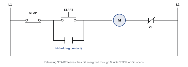
Motor starters are operated by control circuits: start and stop pushbuttons, limit and pressure switches, interlocks and the coil of the contactor, often supplied at 120 V (or 24 V) from a control transformer in the starter. Control circuits need their own overcurrent protection, sized for the small conductors used (often 14 or 16 AWG), and should be designed so that a ground fault cannot start the motor or prevent it from stopping: the coil is connected to the grounded side, and the switches to the ungrounded side. A typical three-wire control with a holding (seal-in) contact also provides undervoltage protection: after a power loss, the motor does not restart until the start button is pressed again, which protects workers from unexpected restarts.
Variable-frequency drives
Variable-frequency drives (VFDs) supply motors through a rectifier and inverter (ELE-370). The conductors to the drive are sized for the drive's rated input current, which can exceed the motor's current because of harmonics and drive losses, and the drive often provides electronic motor overload protection. Output conductors carry high-frequency switching voltages, so cable type, length limits, shielding and grounding follow the manufacturer's instructions, and motors must be suitable for inverter duty.
Part X of Article 430 covers adjustable-speed drive systems: conductors supplying a power conversion unit are sized at not less than 125% of its rated input current (430.122(A)), and the drive may provide the motor overload protection if it is identified for that purpose.
Worked problem
Conductors to a drive
A drive for a 50 hp motor has a rated input current of 72 A. What ampacity is needed for its supply conductors?
Show solution
- \(1.25 \times 72 = 90\) A.
Answer: At least 90 A, larger than the 125% of the motor's table full-load current would require at 460 V (81 A) or 575 V (65 A). Drive input currents are given in the drive documentation and must be used.
Verifying a motor installation
Before a new motor is put into service, the electrician checks that the installation matches the design and the code, and that the motor will run as intended. A typical commissioning sequence is:
- Compare the motor nameplate (voltage, full-load current, service factor, code letter, temperature rise) with the drawings and with the settings of the overload relay; the relay is set from the nameplate current, not the table value.
- Confirm the short-circuit protective device type and rating, and that the starter, disconnect and drive are rated for the available fault current marked on the equipment.
- Test insulation resistance of the motor windings and feeder conductors with an insulation tester at a voltage suited to the equipment, and record the readings so later tests can show deterioration.
- Check torque on terminations, the equipment grounding conductor and bonding of the motor frame.
- Verify the control circuit: the stop button, overload contact and any safety interlocks must each drop out the contactor.
- Bump the motor briefly to confirm rotation before coupling it to the load; reverse any two supply conductors if it turns the wrong way.
- Measure running current on each phase under load and compare with the nameplate; a current imbalance of more than a few percent points to voltage unbalance or a winding problem.
Worked problem
Checking current imbalance
A motor draws 41, 44 and 38 A on its three phases. What is the current imbalance?
Show solution
- Average: \((41 + 44 + 38)/3 = 41\) A.
- Maximum deviation: \(44 - 41 = 3\) A, and \(41 - 38 = 3\) A.
- Imbalance: \(3/41 = 7.3\%\).
Answer: About 7.3%, high enough to investigate. Rolling the leads (moving each conductor one terminal over) shows whether the imbalance follows the supply or the motor: if the high reading moves with the supply conductor, the cause is upstream.
Lesson 4 widens the view to overcurrent protection and fault current throughout the system, and Lesson 8 covers industrial control panels and machine safety.
Common mistakes
MistakeUsing nameplate current to size conductors and short-circuit protection.
InsteadUse the code table full-load current; use nameplate current only for overloads.
MistakeChoosing a breaker at 125% of motor current.
InsteadShort-circuit protection is sized by the table percentages so the motor can start; overloads handle overload.
MistakeRaising overload settings to stop nuisance trips without finding the cause.
InsteadInvestigate voltage, load and ventilation; stay within code limits.
MistakePlacing the disconnect out of sight without lockable provisions.
InsteadKeep it within sight or make it lockable as the code permits.
MistakeSizing drive supply conductors from the motor current.
InsteadUse 125% of the drive's rated input current.
Summary and key terms
- Motor circuits separate short-circuit protection, overload protection, conductors, controller and disconnect.
- Table full-load currents size conductors, short-circuit devices and disconnects; nameplate currents size overloads.
- 430.22: conductors at 125% of FLC; 430.32: overloads at 115–125% of nameplate.
- Table 430.52 limits short-circuit devices (for example 250% for inverse-time breakers), next higher size permitted.
- Feeders use 125% of the largest motor plus the others; feeder devices use the largest branch device plus other FLCs, next lower size.
- Disconnects must be within sight or lockable open.
- Three-wire control provides undervoltage protection; control circuits need their own protection.
- Drive supply conductors are sized at 125% of the drive input current.
- Full-load current (FLC)
- The code table current for a motor of a given horsepower and voltage.
- Full-load amps (FLA)
- The current marked on a motor's nameplate.
- Overload relay
- A device that trips on sustained overcurrent to protect a motor.
- Service factor
- A multiplier indicating permissible continuous overload.
- Inverse-time breaker
- A breaker that trips faster as current increases.
- Dual-element fuse
- A time-delay fuse that tolerates starting current but opens on faults.
- Motor circuit protector
- An instantaneous-trip breaker used with a listed starter.
- In sight
- Visible and within a specified distance.
- Holding contact
- An auxiliary contact that keeps a contactor energized after the start button is released.
- Undervoltage protection
- Prevention of automatic restart after a power failure.
Practice problems
Work each problem on paper first, then reveal the answer to check.
Conductor ampacity for a 10 hp, 460 V motor (FLC 14 A)?
Show answer
17.5 A; 14 AWG copper is adequate for ampacity.
Nameplate 40 A, service factor 1.0, temperature rise 50 °C. Maximum overload setting?
Show answer
115%: 46 A.
Maximum time-delay fuse for the 10 hp, 460 V motor?
Show answer
1.75 × 14 = 24.5 A; next higher standard 25 A.
Why can a motor breaker be larger than the conductor ampacity?
Show answer
The overload relay protects the conductors against overload; the breaker only protects against faults.
Feeder for motors with FLC 40 A, 20 A and 20 A. Minimum ampacity?
Show answer
1.25 × 40 + 20 + 20 = 90 A.
Largest branch breaker 100 A, other FLCs 20 A and 20 A. Maximum feeder breaker?
Show answer
140 A; 140 is a standard size.
Which current is used for overload sizing?
Show answer
The motor nameplate full-load current.
What does a holding contact do?
Show answer
It keeps the contactor energized after the start button is released, and drops out on power loss.
A drive has a rated input current of 48 A. Supply conductor ampacity?
Show answer
60 A.
What standard governs lockout procedures?
Show answer
CSA Z460 in Canada; OSHA 1910.147 in the US.
Lesson quiz · 5 questions
Score 60% or more to complete this lesson.
Create a free account to save your progress, take quizzes and earn a certificate.