
ELEC-220 · Lesson 10 of 12 · 29 min
Fire alarm, communication and low-energy systems
Commercial and industrial buildings contain far more than power wiring. Fire alarm systems detect fires and warn occupants; communication cabling carries data, voice and building automation signals; and many control and signaling circuits run at low, power-limited voltages, including the Power over Ethernet circuits that now supply lighting, cameras, wireless access points and even desk equipment. These systems have their own code sections, product standards and installation rules, and in many jurisdictions electricians install them alongside or instead of specialty contractors. This lesson covers fire alarm system components and circuits, power supplies and battery calculations, survivability and interconnections with other building systems, verification and testing, and the rules for power-limited circuits, communication cabling and Power over Ethernet.
Fire alarm systems
A fire alarm system has a control unit (panel) that monitors initiating devices, activates notification appliances, and communicates with the fire department or a monitoring station. Its parts:
- Initiating devices: manual pull stations, smoke detectors (photoelectric and ionization), heat detectors (fixed temperature and rate of rise), duct smoke detectors, sprinkler waterflow switches and supervisory devices such as valve tamper switches.
- Notification appliances: horns, bells, speakers, and visual signals (strobes) for occupants who are deaf or hard of hearing; voice evacuation systems give spoken instructions, used in high-rise and large assembly buildings.
- Ancillary functions: releasing magnetic door holders so that fire doors close, recalling elevators, shutting down air handlers or operating smoke control fans, unlocking doors, and signaling sprinkler and suppression systems.
Conventional systems use zones of devices wired on the same circuit, telling the operator only which zone is in alarm. Addressable systems give each device an address on a signaling line circuit (loop), so the panel identifies the exact device, and analog addressable detectors report their sensitivity, allowing drift compensation and maintenance alerts. Almost all new commercial systems are addressable.
In the US, the building and fire codes (IBC and IFC) determine where fire alarm systems are required, NFPA 72, National Fire Alarm and Signaling Code, governs design, installation, testing and maintenance, and NEC Article 760 covers fire alarm wiring, distinguishing power-limited (PLFA) and non-power-limited (NPLFA) circuits and their cable types. Many states license fire alarm installers separately, and NICET certification is widely required for designers and technicians.
Circuits and supervision
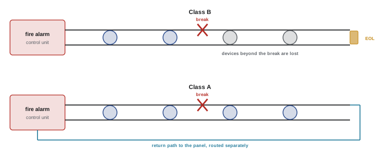
Fire alarm circuits are supervised: the panel continuously monitors them for open circuits, ground faults and, on some circuits, short circuits, and reports a trouble signal if a fault occurs, so that a broken wire is discovered immediately rather than when a fire happens. Conventional initiating and notification circuits use an end-of-line resistor at the far end, through which a small supervisory current flows; an open circuit stops the current and causes a trouble signal. Circuit classes describe performance under faults:
- Class B: a single open circuit disables devices beyond the break, though the panel reports trouble.
- Class A: the circuit returns to the panel by a separate path, so devices on both sides of a single open continue to work. Class A wiring is required in many larger or more important buildings, and the outgoing and return conductors must be routed separately so that one incident cannot damage both.
- Class X and other classes in current standards add protection against shorts and ground faults with isolators.
Short-circuit isolators on addressable loops limit the effect of a short to the section between two isolators.
Notification appliance circuits and voltage drop
Notification appliance circuits (NACs) carry substantial current to horns and strobes, and the voltage at the last appliance must stay above the appliance's minimum operating voltage when the battery is near the end of its discharge (about 20.4 V on a 24 V system). Voltage drop calculations are therefore essential, often using the "lumped load" method that conservatively places all the load at the end of the circuit.
Worked problem
NAC voltage drop
A NAC supplies 16 strobes drawing 0.12 A each over 90 m of 14 AWG copper (about 8.3 Ω/km per conductor). The panel output is 20.4 V at end of battery discharge, and the strobes need at least 16 V. Using the lumped-load method, is the circuit acceptable?
Show solution
- Total current: \(16 \times 0.12 = 1.92\) A.
- Loop resistance (out and back): \(2 \times 0.090 \times 8.3 = 1.49\) Ω.
- Voltage drop: \(1.92 \times 1.49 = 2.87\) V; voltage at the end \(= 20.4 - 2.87 = 17.5\) V, above 16 V.
Answer: Acceptable, with 1.5 V of margin. If the circuit were 150 m long, the drop would be 4.8 V, leaving 15.6 V, too low; the designer would split the circuit, use 12 AWG conductors or add a NAC extender power supply. Distributed-load calculations give less conservative results when appliances are spread along the circuit.
Power supplies and batteries
Fire alarm systems need a reliable primary supply and secondary (standby) power from batteries or, in some cases, an emergency generator, so that they work during a power failure. Codes require the batteries to supply the system in its normal standby condition for a specified time, followed by full alarm load for a specified time, typically 24 hours of standby plus 5 minutes of alarm in many cases (with longer alarm times, such as 15 or 30 minutes, for voice systems and some occupancies, and different requirements where a generator is provided). The required capacity is:
where \(F\) is a safety factor for aging and temperature, typically 1.2 to 1.25.
Worked problem
Battery sizing
A panel and its devices draw 0.85 A in standby and 6.2 A in alarm. The system requires 24 hours of standby followed by 30 minutes of alarm. Using a factor of 1.2, what battery capacity is needed?
Show solution
- Standby: \(0.85 \times 24 = 20.4\) Ah.
- Alarm: \(6.2 \times 0.5 = 3.1\) Ah.
- Total with factor: \((20.4 + 3.1) \times 1.2 = 28.2\) Ah.
Answer: At least 28.2 Ah, so a pair of 12 V, 33 Ah batteries in series would be selected (the next standard size above 28.2 Ah). Battery date codes and capacity tests are part of annual inspection, since sealed lead-acid batteries lose capacity over three to five years.
Survivability and wiring methods
In larger buildings, especially high-rises and buildings with voice evacuation or staged evacuation, circuits that must keep working during a fire, such as risers to notification circuits on floors not yet affected, need survivability: protection so that a fire in one area does not disable the system elsewhere. Methods include two-hour rated fire separations around risers, two-hour circuit integrity cable (cables tested to keep operating in a fire, such as mineral-insulated cable or listed circuit integrity cable systems), and routing outgoing and return Class A paths separately. Fire alarm conductors are identified (often by red cable jackets or red-painted raceways and boxes) and separated from other circuits as the code requires.
Interfaces with other building systems
Fire alarm systems coordinate with many other systems: sprinkler waterflow and valve supervision, kitchen and special-hazard suppression systems, elevator recall (with smoke detectors in elevator lobbies, machine rooms and shafts initiating recall to a designated floor), air handler shutdown by duct detectors, smoke control systems, magnetic door holders, access-controlled doors that must unlock, and generator and fire pump status. Each interface must be designed, installed and tested so that it works in the right sequence. The sequence of operations, often shown in a matrix of inputs and outputs, is one of the most important documents for a fire alarm system, and integrated testing of all interfaces before occupancy is required in many jurisdictions.
Verification and testing
New fire alarm systems are verified before occupancy: every device is tested for correct operation and indication at the panel, every circuit is checked for supervision, battery capacity and charger operation are confirmed, sound levels and strobe coverage are measured, interfaces are tested, and a verification report is issued. In Canada this is done to CAN/ULC-S537 by qualified technicians, and in the US to NFPA 72 acceptance testing requirements. Existing systems are inspected and tested annually, with some items tested more often, to CAN/ULC-S536 or NFPA 72, and records kept. Electricians installing fire alarm wiring should test insulation resistance and continuity before devices are connected, label circuits, and provide as-built drawings for the verification technician.
Power-limited (Class 2) circuits
Many control and signaling circuits are supplied by sources whose output is inherently limited, so that they present little risk of fire or electric shock: thermostats, doorbells, security systems, building automation controls, LED lighting drivers with Class 2 outputs, and low-voltage lighting. The code classifies these as Class 2 circuits (and, in the US, Class 3 for somewhat higher voltages with limited power), typically limited to about 100 VA and to voltages of 30 V AC or 60 V DC in dry locations for Class 2. Because of their low energy, they can be wired with lighter cables and fewer protections than power circuits, but they must be kept separate from power and lighting circuits (in separate raceways or compartments, or separated by barriers or distance), so that a fault cannot energize the Class 2 wiring at line voltage.
In the 2023 NEC, Article 722 covers cables for power-limited circuits, Article 724 Class 1 circuits, and Article 725 Class 2 and Class 3 circuits, with 725.144 addressing bundles of 4-pair cables that transmit power and data. Articles 800 to 840 cover communication circuits, coaxial cable and network-powered broadband.
Communication cabling and Power over Ethernet
Structured cabling for data and voice follows standards such as ANSI/TIA-568 (adopted in Canada as CSA T529) for horizontal cabling from telecommunications rooms to outlets (maximum 90 m permanent link plus patch cords, 100 m channel), backbone cabling, pathways and spaces, labeling and testing. Category 6 and 6A copper cables support 1 and 10 gigabit Ethernet; optical fiber is used for backbones and long runs. Electricians installing communication cabling must respect bend radius and pulling tension limits, avoid crushing cables with tight ties, keep cables away from sources of interference such as fluorescent ballasts and motors, use plenum-rated or appropriately fire-rated cable for the space, firestop penetrations (Lesson 2), and test each link with a certified tester.
Power over Ethernet (PoE) delivers DC power over the same twisted pairs, with standards up to about 90 W at the source (IEEE 802.3bt Type 4) for devices such as LED luminaires, pan-tilt-zoom cameras, wireless access points and displays. Large bundles of PoE cables heat up because each conductor carries current, so the code and cabling standards limit bundle sizes or require cables with higher temperature ratings or larger conductors for high-power PoE, and recommend avoiding tightly packed bundles in enclosed spaces.
Worked problem
PoE power budget
A ceiling with 48 PoE LED luminaires, each needing 38 W at the device, is supplied from two 24-port switches. Cable losses are about 10% at the maximum run. What PoE power budget must each switch provide?
Show solution
- Each switch powers 24 luminaires: \(24 \times 38 = 912\) W at the devices.
- At the source, allowing for 10% cable loss: \(912/0.9 = 1{,}013\) W.
Answer: About 1,000 W of PoE budget per switch, which requires switches designed for high-power 802.3bt PoE with adequate power supplies, often redundant. The cable bundles, each of up to 24 cables carrying nearly 40 W, must be checked against the code and standard bundle limits, and the switches need backup power if the lighting includes emergency lighting (Lesson 9).
Common mistakes
MistakeRunning fire alarm circuits without end-of-line devices or supervision.
InsteadInstall supervised circuits with end-of-line devices as the panel and standard require.
MistakeIgnoring voltage drop on notification circuits.
InsteadCalculate drop at end-of-discharge voltage and split or upsize circuits as needed.
MistakeRouting Class A outgoing and return conductors together.
InsteadRoute them separately so one incident cannot damage both.
MistakeMixing Class 2 wiring with power conductors in the same raceway or box.
InsteadSeparate them by raceway, barrier or distance as required.
MistakeBundling large numbers of high-power PoE cables tightly.
InsteadFollow bundle limits and use cable rated for the PoE temperature rise.
Summary and key terms
- Fire alarm systems combine initiating devices, notification appliances, a control unit and ancillary functions; addressable systems identify each device.
- Circuits are supervised for faults; Class A paths keep working after a single open.
- NAC voltage drop must leave appliances above their minimum voltage at end of battery discharge.
- Batteries are sized for standby plus alarm time with a safety factor.
- Survivability, interfaces with other systems, verification and periodic testing are essential.
- Class 2 circuits have limited power and must be separated from power circuits.
- Structured cabling follows TIA-568 (CSA T529); PoE delivers up to about 90 W per port and needs attention to bundle heating.
- Initiating device
- A device that signals an alarm, such as a detector or pull station.
- Notification appliance
- A horn, speaker or strobe that warns occupants.
- Addressable system
- A fire alarm system in which each device has a unique address.
- Supervision
- Continuous monitoring of circuits for faults.
- End-of-line resistor
- A resistor at the end of a circuit allowing supervision current to flow.
- Class A circuit
- A circuit with a return path that continues working after a single open.
- Survivability
- Protection of circuits so they keep working during a fire.
- Class 2 circuit
- A power-limited circuit with reduced fire and shock risk.
- Structured cabling
- Standardized telecommunications cabling for buildings.
- Power over Ethernet
- DC power delivered over twisted-pair data cabling.
Practice problems
Work each problem on paper first, then reveal the answer to check.
What is the advantage of an addressable system?
Show answer
The panel identifies the exact device in alarm or trouble.
What happens after a single open on a Class B circuit?
Show answer
Devices beyond the break are disabled; trouble is reported.
Voltage drop for 2.4 A over a 1.2 Ω loop?
Show answer
2.9 V.
Battery for 1.1 A standby for 24 h and 4 A alarm for 5 min, factor 1.2?
Show answer
\((26.4 + 0.33) \times 1.2 = 32.1\) Ah.
Name two survivability methods.
Show answer
Rated shafts or enclosures, circuit integrity cable, separate routing.
Name three fire alarm interfaces.
Show answer
Elevator recall, door holders, HVAC shutdown, sprinkler supervision.
Which Canadian standard covers verification of new fire alarm systems?
Show answer
CAN/ULC-S537.
Typical power limit of a Class 2 circuit?
Show answer
About 100 VA.
Maximum horizontal permanent link length in structured cabling?
Show answer
90 m.
Why are PoE bundle sizes limited?
Show answer
Current in every cable heats the bundle.
Lesson quiz · 5 questions
Score 60% or more to complete this lesson.
Create a free account to save your progress, take quizzes and earn a certificate.