
ELE-499 · Lesson 6 of 12 · 20 min
Protection, grounding and electrical safety
Hannah's part of the project had two halves that met in the middle. For the full-size canopy, she was responsible for making the design safe and code-compliant: conductor and breaker sizing, fault ratings, grounding and bonding, the protection that keeps the canopy from exporting, and the labeling that warns people of hazards. For the laboratory demonstrator, she was the team's safety officer, responsible for making sure that four students working on a 400 V, 6 kW converter went home uninjured every day. This lesson covers both.
Which rules apply
In Wisconsin, electrical installations follow the state's electrical code, which adopts the National Electrical Code (NFPA 70) with state amendments; the state's update to the 2023 edition took effect on September 1, 2026. Several articles matter most for the canopy. Article 690 covers photovoltaic systems, Article 706 energy storage systems, Article 625 electric vehicle power transfer systems, and Article 705 interconnected power production sources. Articles 220 and 240 set out load calculations and overcurrent protection, and Article 250 covers grounding and bonding. Storage installations must also meet the fire code, which in most jurisdictions references NFPA 855. Equipment must be listed by a nationally recognized testing laboratory, and the installation is inspected by the authority having jurisdiction before it is energized.
Two things about this regime surprise students. First, the code is a minimum, written for safety, not a design guide; meeting it does not make a design good. Second, the authority having jurisdiction, the inspector, has the final word on interpretation. Where the team was unsure whether a rule applied, for example to a free-standing parking canopy rather than a building, Hannah wrote down the question, the team's interpretation and the reasoning, and Larchmont's electrical contractor checked it with the inspector before the design was finalized.
Continuous loads and conductor sizing
Electric vehicle chargers and inverter output circuits are continuous loads: they can run at full current for three hours or more. The NEC requires overcurrent devices and conductors for continuous loads to be rated at not less than 125 % of the continuous current, and Articles 625, 690 and 706 apply the same idea to chargers, PV output and storage circuits. The team applied the rule to each feeder, then chose conductors whose ampacity, from the code's tables for copper with 75 °C terminations, was at least the breaker rating.
# Feeder sizing with the 125 % continuous-load rule and an available-fault-current check (480 V service, Madison)
import math
V = 480.0                                    # three-phase service voltage, V
AMPACITY = [('8 AWG', 50), ('6 AWG', 65), ('4 AWG', 85), ('3 AWG', 100), ('2 AWG', 115), ('1 AWG', 130),
            ('1/0 AWG', 150), ('2/0 AWG', 175), ('3/0 AWG', 200)]   # copper, 75 C column, typical tabulated values
OCPD = [15, 20, 30, 40, 50, 60, 70, 80, 90, 100, 110, 125, 150, 175, 200]
loads = [('hybrid inverter 100 kVA', 100e3, 1.0), ('DC fast charger 60 kW', 60e3 / 0.94, 1.0)]
def size(name, va, pf):
    i = va / (math.sqrt(3) * V)
    need = 1.25 * i                          # continuous load: 125 % of the full-load current
    br = next(b for b in OCPD if b >= need)
    cond = next(c for c, a in AMPACITY if a >= br)
    print(f"{name:26s} I = {i:6.1f} A, x1.25 = {need:6.1f} A -> breaker {br} A, conductors {cond}")
for l in loads: size(*l)
l2 = 48.0; print(f"Level 2 charger, 48 A continuous at 208 V from the step-down transformer -> {1.25 * l2:.0f} A circuit")
# available fault current at the new panel from the 300 kVA, 5 % impedance service transformer
kva, z = 300e3, 0.05
isc_utility = kva / (math.sqrt(3) * V * z)
isc_inv = 1.2 * 100e3 / (math.sqrt(3) * V)    # inverter contribution, about 1.2 per unit
print(f"utility fault current {isc_utility / 1000:.1f} kA + inverter {isc_inv / 1000:.2f} kA = {(isc_utility + isc_inv) / 1000:.1f} kA")
for rating in (10, 14, 18, 22, 25):
if rating * 1000 >= isc_utility + isc_inv: print(f"choose breakers and panel rated at least {rating} kA"); breakhybrid inverter 100 kVA I = 120.3 A, x1.25 = 150.4 A -> breaker 175 A, conductors 2/0 AWG DC fast charger 60 kW I = 76.8 A, x1.25 = 96.0 A -> breaker 100 A, conductors 3 AWG Level 2 charger, 48 A continuous at 208 V from the step-down transformer -> 60 A circuit utility fault current 7.2 kA + inverter 0.14 kA = 7.4 kA choose breakers and panel rated at least 10 kA
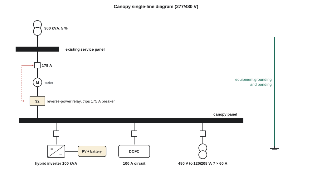
At 480 V, the 100 kVA hybrid inverter draws about 120 A, so its circuit needs a 175 A breaker and 2/0 AWG copper; the 60 kW fast charger, about 77 A, needs a 100 A breaker and 3 AWG; and each 48 A Level 2 charger needs a 60 A circuit. These are starting points. The final sizes also account for ambient temperature correction, the number of current-carrying conductors in each raceway, voltage drop over the run from the service panel to the canopy, and the charger and inverter manufacturers' instructions, which can require larger breakers than the code minimum.
Worked problem
Size a charger circuit
A charger draws 32 A continuously. What minimum breaker rating applies, and what is the next standard size?
Show solution
- \[I_{min} = 1.25 \times 32 = 40\ \text{A}\]
- 40 A is itself a standard breaker size.
Answer: A 40 A breaker, with conductors rated at least 40 A at the termination temperature.
Fault current and equipment ratings
Every breaker, panel and piece of equipment must be able to withstand and, where it interrupts, clear the largest fault current available at its location. The program estimates the available fault current at the canopy panel from the service transformer alone, assuming an infinite utility source behind it, which is conservative. The inverters add a small contribution of their own, about 1.2 times rated current for a few cycles, as Leo had learned in his protection term. The result is well within the 10 kA rating of standard commercial breakers and panels.
At 480 V the transformer can supply about 7.2 kA, and the inverter adds about 0.1 kA. Hannah still asked Larchmont for the actual transformer impedance and the conductor run from it, because the breaker ratings in the existing service panel set an upper limit on what can be added to it, and because the arc-flash study below needs the real number.
Zero export and the protective relay
Requirement R8 says the canopy must never export power to Larchmont's distribution system. The hybrid inverter can limit export by itself, measuring power at the service with its own current sensors and reducing output when export appears. But Nadine pointed out what Leo would later write about in his interconnection study: a control function can fail, and the whole reason for choosing zero export was to avoid a full interconnection review, which assumes the export limit always holds. Larchmont therefore required a separate protective relay at the canopy's connection, independent of the inverter, set to trip the canopy breaker if reverse power flow exceeded a small threshold for a short time.
The relay uses a reverse-power element, device 32 in the standard numbering, with a pickup of about 1 kW and a delay of about two seconds, which ignores the brief export transients that occur when a large charger suddenly stops while the inverter is at full output, but trips well before sustained export could affect the feeder. Ravi helped Hannah pick the relay and its current and voltage transformers. In lesson 10 the team tests it with a relay test set before the demonstrator is ever connected.
Grounding and bonding
The canopy is supplied from a solidly grounded wye service. All exposed metal, the canopy's steel structure, the module frames, racking, enclosures and charger pedestals, is bonded together and to the service grounding system through equipment grounding conductors, so that a fault from a live conductor to metal draws enough current to trip the breaker quickly. The steel canopy columns are also bonded to a grounding electrode at the structure. On the DC side, the solar array and battery have their own ground-fault detection, and the code's requirements for PV systems include protection against DC arc faults, which are hard to extinguish because direct current has no natural zero crossing.
Electric vehicle chargers bring a specific personnel hazard: a user handles a cable and connector outdoors, often in rain or snow. Chargers therefore include charge-circuit interrupting devices that detect small ground-fault currents and open the circuit, and the connector is designed so that its contacts are not energized until the vehicle has confirmed a proper connection. The team's job was to make sure the chargers they specified were certified for this use and installed as their instructions required, not to redesign these safety functions.
Arc flash and labeling
Anyone working on energized equipment in the canopy panel or the inverter enclosure could be exposed to an arc flash. Larchmont's own safety program, like any employer's, requires an arc-flash risk assessment and labels on equipment showing the incident energy or the required protective equipment category, the arc-flash boundary and the shock approach boundaries. Hannah did a first estimate using the method Leo had learned in ELE-480 and recommended that Larchmont's engineering group include the canopy in its next formal study. She also specified that the canopy's equipment be arranged so that routine tasks, such as resetting a charger or reading the inverter display, can be done with the doors closed.
In the United States, workplace electrical safety follows NFPA 70E, Standard for Electrical Safety in the Workplace, which OSHA relies on in enforcing its electrical safety rules.
Safety in the laboratory
The demonstrator's 400 V DC bus is lethal, and its capacitors hold charge after the supply is off. Hannah wrote the team's laboratory safety plan in week ten, and the advisor and the department's safety officer approved it before any power was applied. Its main rules were that nobody works on the converter alone; that the converter runs only inside a closed, grounded enclosure with an interlocked lid that opens the contactor and starts the bus discharge; that the supply is locked out and the bus voltage measured at zero with a meter checked on a known source before anyone touches the board; that measurements on a live board use differential probes or isolated equipment, never a grounded oscilloscope clipped to a floating node; and that every test follows a written procedure with a stop condition. A large red emergency stop on the bench removes power from the supply and the battery contactor.
Batteries have their own hazards. The laboratory battery's terminals were covered, its cables were fused at the battery, and the team followed the battery supplier's handling instructions. A lithium-ion cell driven into thermal runaway can release flammable and toxic gas, so the battery sat in a ventilated cabinet away from the bench, with its management system's protections always active.
The safety plan also listed who could do what. Only Aisha and Hannah, who had completed the department's high-voltage laboratory training, could connect or disconnect power-stage wiring. Leo and Mateo could run tests under a written procedure once the enclosure was closed. This kind of explicit authorization is normal in industry and makes it easy for anyone to say \"stop\".
Common mistakes
MistakeTreating the electrical code as a design guide.
InsteadThe code sets minimum safety requirements; good design goes further.
MistakeSizing continuous-load circuits at 100 % of current.
InsteadUse 125 %, or 80 % loading of the breaker, unless equipment is marked for 100 % duty.
MistakeRelying on the inverter's export limit alone.
InsteadBack up control functions with an independent protective relay when the system's approval depends on them.
MistakeWorking on a converter after switching off the supply.
InsteadLock out, wait for discharge, and verify zero voltage with a tested meter before touching.
Summary and key terms
- In Wisconsin the state electrical code adopts the NEC; Articles 690, 706, 625, 705, 220, 240 and 250 matter most for the canopy.
- The inspector has the final word on interpretation; record and check uncertain points.
- Continuous loads such as chargers and inverter outputs are sized at 125 % of current.
- Equipment ratings must exceed the available fault current at their location.
- A reverse-power relay backs up the inverter's export limit.
- Bonding all exposed metal ensures faults trip protection quickly.
- A written laboratory safety plan, interlocks, lockout and verification protect the team.
- Continuous load
- A load whose maximum current is expected to continue for three hours or more.
- Ampacity
- The current a conductor can carry continuously without exceeding its temperature rating.
- Available fault current
- The largest current that can flow at a point during a short circuit.
- Reverse-power relay (device 32)
- A relay that operates when power flows in the opposite direction to normal.
- Bonding
- Connecting conductive parts so that they are at the same potential and can carry fault current.
- Authority having jurisdiction (AHJ)
- The inspector or agency responsible for enforcing the code.
- Arc-flash boundary
- The distance from exposed live parts within which a person could receive a second-degree burn.
Practice problems
Work each problem on paper first, then reveal the answer to check.
A charger draws 48 A continuously. What breaker size applies?
Show answer
1.25 × 48 = 60 A.
Why might the final conductor be larger than the table choice?
Show answer
Temperature correction, conductor fill, voltage drop or manufacturer instructions.
Why is the transformer fault estimate conservative?
Show answer
It assumes an infinite utility source behind the transformer.
Why does the reverse-power relay have a two-second delay?
Show answer
To ignore brief export transients when a charger stops suddenly.
What must happen before anyone touches the demonstrator's board?
Show answer
Lockout, bus discharge and verification of zero voltage with a tested meter.
Why should oscilloscope ground clips never connect to a floating node?
Show answer
They tie the node to earth through the scope, causing a short circuit or shock hazard.
Lesson quiz · 5 questions
Score 60% or more to complete this lesson.
Create a free account to save your progress, take quizzes and earn a certificate.