
ELE-490 · Lesson 9 of 12 · 22 min
Protection with inverter-based resources
During his protection term Leo helped Nadine Cormier set the relays for feeder F3, whose 9.9 MW solar plant needed directional elements, a longer reclosing dead time and direct transfer trip. Now the same questions return for Birch Hill, and Nadine joins the study team to review them. \"The protection problems with inverters are not the same ones we had with synchronous generators,\" she tells him. \"Some are smaller, some are bigger, and a few are new.\" This lesson works through them: what fault current an inverter supplies, how it affects feeder relays and fuses, sympathetic tripping, reclosing and islanding, grounding and overvoltage, and what changes on the transmission system.
What an inverter supplies during a fault
A synchronous generator behaves during a fault as a voltage behind its subtransient reactance, delivering a current several times its rating that decays over a few cycles to seconds. An inverter does what its control tells it, within its semiconductor limits. Grid-following inverters typically limit fault current to about 1.1 to 1.5 times rated, reach that level within a cycle or two, and hold it steady rather than decaying. Under ride-through requirements they must keep injecting current during the fault, and modern settings direct most of it as reactive current to support voltage.
Two details matter for protection. First, many inverters inject only positive-sequence current, or a small, controlled amount of negative-sequence current, during unbalanced faults. Protection elements that rely on negative-sequence quantities, such as directional elements and some fault-type selection logic, may then behave differently near an inverter-dominated source than near a synchronous generator. IEEE 2800-2022 addresses this for transmission-connected plants by requiring a controlled negative-sequence current response. Second, an inverter's fault current depends on its control mode and firmware, so the utility must obtain manufacturer data or test results rather than assume a value.
Fault current on the feeder: reduced reach
When a generator sits between a feeder relay and a fault, it supplies part of the fault current from the downstream side, and the relay at the substation sees less current than it would without the generator. This effect, called protection blinding or reduced reach, can delay or prevent tripping for faults near the end of the feeder. It is the distribution counterpart of the infeed effect on distance relays that Leo studied in his protection term. With large synchronous generators it can be severe; with inverters, whose current is limited, it is usually modest.
import cmath, math
V = 24.94e3; E = V/math.sqrt(3)                      # phase voltage, V
Zs = cmath.rect(V**2/(math.sqrt(3)*V*5.62e3), math.atan(10))   # 25 kV source, 5.62 kA, X/R 10
zkm = complex(0.11, 0.40)
I_IBR = 1.2*10e6/(math.sqrt(3)*V)                    # Birch Hill fault current limit, A (1.2 pu)
def fault(fault_km, poi_km=11, ibr=True):
    """Three-phase fault on F2 beyond the POI; returns source-side current and POI voltage."""
    Za = Zs + zkm*poi_km; Zb = zkm*(fault_km - poi_km)
    vp = E*Zb/(Za + Zb)                              # first guess without the plant
    for _ in range(50):
        i_ibr = cmath.rect(I_IBR, cmath.phase(vp) - math.pi/2) if ibr else 0   # reactive current injection
        vp = (E/Za + i_ibr)/(1/Za + 1/Zb)
    return abs((E - vp)/Za), abs(vp)/E
print("Fault beyond Birch Hill (plant at 11 km): current seen by the breaker and recloser R2")
for km in (12, 14, 18):
    a, _ = fault(km, ibr=False); b, vp = fault(km)
    print(f"  3-phase fault at {km:2d} km: {a:6.0f} A without plant, {b:6.0f} A with plant "
          f"({(b - a)/a*100:+5.1f} %), POI voltage {vp:.2f} pu")
# Sympathetic tripping check: fault on F1 near the bus, plant current flows back through F2's breaker
print(f"Birch Hill fault current {I_IBR:.0f} A flowing back through F2's breaker; "
      f"F2 51P pickup 288 A -> margin {288 - I_IBR:.0f} A")
# Reclosing: does the island outlast the dead time?
for dead in (0.5, 1.0, 3.0, 5.0):
print(f" recloser dead time {dead:3.1f} s vs 2 s anti-islanding limit: {'unsafe - plant may still energize the line' if dead <= 2.0 else 'plant must already have ceased'}")Fault beyond Birch Hill (plant at 11 km): current seen by the breaker and recloser R2 3-phase fault at 12 km: 1916 A without plant, 1901 A with plant ( -0.7 %), POI voltage 0.06 pu 3-phase fault at 14 km: 1726 A without plant, 1687 A with plant ( -2.2 %), POI voltage 0.17 pu 3-phase fault at 18 km: 1440 A without plant, 1364 A with plant ( -5.3 %), POI voltage 0.33 pu Birch Hill fault current 278 A flowing back through F2's breaker; F2 51P pickup 288 A -> margin 10 A recloser dead time 0.5 s vs 2 s anti-islanding limit: unsafe - plant may still energize the line recloser dead time 1.0 s vs 2 s anti-islanding limit: unsafe - plant may still energize the line recloser dead time 3.0 s vs 2 s anti-islanding limit: plant must already have ceased recloser dead time 5.0 s vs 2 s anti-islanding limit: plant must already have ceased
The program models a three-phase fault on F2 beyond Birch Hill's 11 km point of interconnection, with the plant injecting 278 A of reactive current, 1.2 times its rated current. For a fault at 12 km, just past the plant, the breaker's current falls by under 1 %. For a fault at the end of the feeder it falls by about 5 %, from 1440 A to 1364 A. F2's phase and ground elements and R2's curves still see the fault with ample margin. Reduced reach is not Birch Hill's binding protection problem.
The same calculation for a 10 MW synchronous generator, with a subtransient current of perhaps six times rated, would show a much larger reduction, which is why older interconnection guides devoted so much attention to it. The lesson for inverter-based plants is to calculate rather than assume: on a long feeder with several large inverter plants, or with a fuse at the very end of its reach, even a modest reduction can matter.
Sympathetic tripping
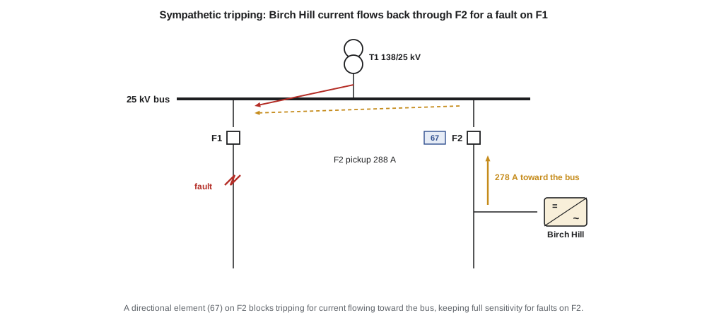
Sympathetic tripping is the opposite problem. A fault on an adjacent feeder, or on the 25 kV bus, draws fault current from every source connected to the bus, including generators on healthy feeders. Their current flows backward through their own feeder's breaker. If that current exceeds the breaker relay's pickup, a nondirectional relay can trip the healthy feeder, disconnecting its customers and the generator for a fault that was not on it. The program compares Birch Hill's 278 A fault contribution with the pickup of F2's phase time-overcurrent element, 288 A, set during Leo's protection term. The margin is only 10 A, before counting any measurement error or the load current that adds to or subtracts from the generator's current depending on its phase.
Nadine's recommendation is the same as for F3: add a directional element to F2's phase and ground overcurrent protection so that it blocks tripping for current flowing toward the bus. Modern feeder relays include directional elements at no extra hardware cost, so the change is a settings and testing exercise. An alternative, raising F2's pickup, would reduce the relay's sensitivity to genuine faults at the end of the feeder, which is worse.
Fuses, reclosers and fuse saving
Generators on a feeder can also upset coordination between reclosers and lateral fuses. In a fuse-saving scheme, the recloser's fast curve is meant to clear a temporary fault on a lateral before the fuse melts. If a generator downstream of the recloser but upstream of the fuse adds current through the fuse but not through the recloser, the fuse may melt before the recloser's fast curve operates, defeating fuse saving. Birch Hill would connect downstream of recloser R2, and F2's 65T lateral fuse sits at 7 km, upstream of the plant, so for a fault on that lateral the plant's current flows back along the trunk from 11 km to the lateral at 7 km: it passes through the fuse but not through R2, exactly the situation described above. Nadine runs the coordination check and finds the extra current small, but she notes that fuse saving on F2 already fails above about 2.4 kA, and any further reduction of the window would push the utility toward a fuse-blowing philosophy on that lateral.
Reclosing and unintentional islands
Most faults on overhead feeders are temporary: a branch brushes a line, an animal contacts a bushing, or lightning flashes over an insulator. Reclosers and breakers therefore open, wait for a short dead time and close again, restoring service if the fault has cleared. With a generator on the feeder, the reclose becomes dangerous if the generator is still energizing the line when it happens. The generator and the utility source will have drifted apart in phase during the dead time, and closing two unsynchronized sources together causes large currents and torques that can damage the generator, its transformer and the utility's equipment.
Under IEEE 1547-2018 a resource must cease to energize an unintentional island within two seconds. The program compares that limit with several dead times. A first reclose of half a second or one second would happen while Birch Hill might legitimately still be running in a temporary island, which is unsafe. A dead time of three seconds or more falls after the plant must have stopped. Larchmont's practice, already applied to F3, is to extend the first dead time to about three seconds on feeders with large inverter plants, to send direct transfer trip from the recloser or breaker to the plant, and to supervise reclosing with a voltage check on the line side so that the device recloses only onto a dead line.
Worked problem
Choosing the reclose supervision
R2 is set for a first reclose after 3 s, and Birch Hill receives direct transfer trip from R2. The transfer trip channel fails. What protects against an out-of-phase reclose?
Show solution
- The plant's own anti-islanding protection must cease energizing within 2 s.
- Line-side voltage supervision at R2 blocks reclosing if the line is still energized at the end of the dead time.
Answer: The plant's anti-islanding function and dead-line supervision at R2 together provide the backup; the transfer trip is the primary means.
Grounding and overvoltage during ground faults
A ground fault on a four-wire multigrounded feeder raises the voltage of the unfaulted phases by an amount that depends on the system's zero-sequence impedance. With the substation transformer's grounded wye in service, the system is effectively grounded, and the healthy-phase voltages rise only modestly. But once the substation breaker or a recloser opens, the faulted section may remain connected to a generator whose transformer winding offers no ground source on the feeder side, for example a delta winding. The section then behaves as an ungrounded system, and the healthy phases can rise toward full line-to-line voltage, about 1.73 times normal, stressing surge arresters and customer equipment until the generator trips.
Utilities guard against this temporary overvoltage by requiring generators either to provide an effective ground source on the utility side, through a grounded-wye transformer winding or a separate grounding transformer, or to trip quickly enough that the overvoltage does not last. Effective grounding is commonly defined by ratios of zero- to positive-sequence impedance of the system as seen from the fault, roughly X0/X1 of 3 or less and R0/X1 of 1 or less, which limit the healthy-phase voltage to about 1.25 to 1.4 pu. A grounding source, however, also changes the feeder's ground fault currents and the sensitivity of its ground relays, so the choice must be studied. Birch Hill's single-line diagram shows grounded-wye windings on the 25 kV side of each step-up transformer; Nadine asks for their impedances so she can check both the overvoltage and the ground relay settings.
Transmission protection with inverter-based plants
On transmission systems the effects of inverter-based resources are larger, because whole regions may be dominated by them. Distance relays rely on the voltage and current relationship of the source behind them; with an inverter source the current's angle and magnitude are set by control, and a relay may measure an apparent impedance that does not correspond to the fault location. Directional and fault-type logic based on negative-sequence quantities may misoperate if the inverter supplies little negative-sequence current. Current differential protection, which compares currents at both ends of a line, is generally the most robust choice where communication is available. For Larchmont, these concerns apply mainly to the Hollis Ridge plant and future large transmission plants, but the study notes that reverse flow from Lincoln Road into the 138 kV system should be checked against the 138 kV relays' directional settings.
Common mistakes
MistakeAssuming inverter fault current is negligible.
InsteadIt is limited but real, typically 1.1 to 1.5 times rated, and can cause sympathetic tripping.
MistakeAssuming reduced reach from inverters is as severe as from synchronous generators.
InsteadCalculate it; inverter current limits usually keep it modest.
MistakeRaising a feeder relay's pickup to avoid sympathetic tripping.
InsteadAdd a directional element instead, which keeps sensitivity to genuine faults.
MistakeKeeping instantaneous reclosing on a feeder with a large generator.
InsteadExtend the dead time beyond the anti-islanding limit, add transfer trip and supervise reclosing with line voltage.
Summary and key terms
- Grid-following inverters supply limited, controlled fault current, mostly reactive and often mostly positive-sequence.
- Generators between a relay and a fault reduce the relay's current; with inverters the reduction is usually small.
- Generator current flowing back through a healthy feeder's breaker can cause sympathetic tripping; directional elements prevent it.
- Generators can erode fuse-saving coordination between reclosers and lateral fuses.
- Reclosing dead times must exceed the anti-islanding limit, supported by transfer trip and dead-line supervision.
- A generator without a ground source can cause temporary overvoltage on an isolated faulted section.
- On transmission systems, inverter-dominated sources can confuse distance and negative-sequence elements; line differential is robust.
- Protection blinding (reduced reach)
- Reduction of the current seen by a relay because a generator feeds the fault from downstream.
- Sympathetic tripping
- Tripping of a healthy feeder by generator current flowing back toward a fault elsewhere.
- Dead time
- The interval between a recloser or breaker opening and its automatic reclose.
- Dead-line supervision
- Blocking a reclose unless the line side is de-energized.
- Temporary overvoltage
- A power-frequency overvoltage lasting cycles to seconds, such as during a ground fault on an ungrounded section.
- Effective grounding
- Grounding that limits healthy-phase voltage during ground faults, commonly X0/X1 ≤ 3 and R0/X1 ≤ 1.
- Negative-sequence current
- The component of unbalanced current that rotates opposite to normal phase sequence.
Practice problems
Work each problem on paper first, then reveal the answer to check.
A 5 MW inverter plant on a 25 kV feeder has a 1.2 pu current limit. What is its maximum fault current?
Show answer
1.2 × 5/(√3 × 24.94) ≈ 139 A.
Why is reduced reach smaller with inverters than with synchronous generators?
Show answer
Inverters limit their fault current to near rated, while synchronous machines supply several times rated.
Birch Hill's current is 278 A and F2's pickup is 288 A. Why is the margin inadequate?
Show answer
Measurement error and load current can easily exceed 10 A.
Why must the first reclose wait longer than 2 s on feeders with large generators?
Show answer
So that the generator has ceased to energize the island before the reclose.
What can happen to healthy-phase voltage on an isolated section with no ground source?
Show answer
It can rise toward line-to-line voltage, about 1.73 pu.
Which line protection is most robust with inverter-dominated sources?
Show answer
Line current differential.
Lesson quiz · 5 questions
Score 60% or more to complete this lesson.
Create a free account to save your progress, take quizzes and earn a certificate.