
ELE-490 · Lesson 5 of 12 · 21 min
Battery energy storage systems
The battery is what makes Birch Hill more than a solar plant. Five megawatts of inverter capacity backed by 20 MWh of lithium-ion cells can absorb the plant's midday output when the feeder cannot take it, discharge into the evening peak, follow a frequency signal or, in principle, hold up an island. Leo's job in this lesson is to understand the battery as an electrical system: how it is built, how its ratings work, how it is connected, how it might be dispatched to ease the interconnection, and what it requires for safety.
From cells to a battery energy storage system
A battery energy storage system (BESS) is built up in layers. Lithium-ion cells, each a few volts and tens to hundreds of ampere-hours, are assembled into modules, modules into racks, and racks into containers or enclosures. Most new utility systems use lithium iron phosphate (LFP) cells, which are less energy dense than the nickel-manganese-cobalt (NMC) cells common in electric vehicles but have a longer cycle life and are less prone to thermal runaway. Each level has a battery management system (BMS) that measures cell voltages and temperatures, balances cells, estimates the state of charge and opens contactors if anything goes outside safe limits.
The DC battery connects to the grid through a power conversion system (PCS), a bidirectional inverter that can charge or discharge on command, followed by a step-up transformer. Above them sits an energy management system (EMS), the plant-level controller that decides when to charge and discharge, responds to dispatch signals from the utility or market operator and coordinates with the solar plant's controller. Auxiliary systems for heating, ventilation, air conditioning and fire protection draw a significant load of their own, which must be counted in the plant's efficiency.
Power, energy, duration and state of charge
A battery has two independent ratings. Its power rating, in megawatts, is set by the PCS and the cells' current capability: Birch Hill's battery can charge or discharge at up to 5 MW. Its energy rating, in megawatt-hours, is set by the number of cells: 20 MWh. The ratio is the duration, here four hours at full power. Utility batteries are commonly built with durations of one to four hours, with longer durations becoming more common as batteries are used to shift solar output into the evening.
The state of charge (SOC) expresses stored energy as a fraction of usable capacity. Operators rarely use the full range, because deep cycling at very high or very low SOC accelerates aging, so a plant might operate between about 10 and 95 %. Round-trip efficiency, the energy returned divided by the energy put in, is typically about 85 to 90 % at the AC terminals for lithium-ion systems, including PCS and transformer losses, and lower if auxiliary loads are counted. The rate at which a battery is charged or discharged relative to its energy is the C-rate: a four-hour battery at full power runs at 0.25C.
Capacity fades with time and cycling. A common planning figure is a loss of about 1.5 to 3 % of usable energy a year, depending on chemistry, temperature and how hard the battery is cycled. Many owners therefore plan augmentation: adding new modules every few years to keep the usable energy at the contracted value. Birch Hill's application says the developer will augment to maintain 20 MWh, an important detail if the utility's study relies on the battery's full energy.
AC coupling and DC coupling
A battery can be paired with a solar plant in two ways. In an AC-coupled plant, like Birch Hill, the battery has its own PCS and connects on the AC side of the solar inverters, typically at the plant's collector bus. The two systems can be controlled and maintained independently, and the battery can charge from the grid as easily as from the solar plant. In a DC-coupled plant, the battery connects through a DC-DC converter to the DC bus of the solar inverter. The battery can then capture energy that the array produces above the inverter's AC limit, the clipping described in lesson 2, and the plant needs fewer inverters, but charging from the grid and independent control become more complicated.
The coupling choice matters to the utility mainly through the plant's maximum output at the point of interconnection. An AC-coupled plant with 10 MW of solar inverters and 5 MW of battery inverters could, in principle, export 15 MW if both ran at full output together. Birch Hill's application caps total export at 10 MW, which the plant controller must enforce at all times. Leo flags that the cap must be part of the interconnection agreement, with a protection function or relay setting that backs it up, because a control failure that let the plant export 15 MW would change every result of the study.
Dispatching the battery to ease the interconnection
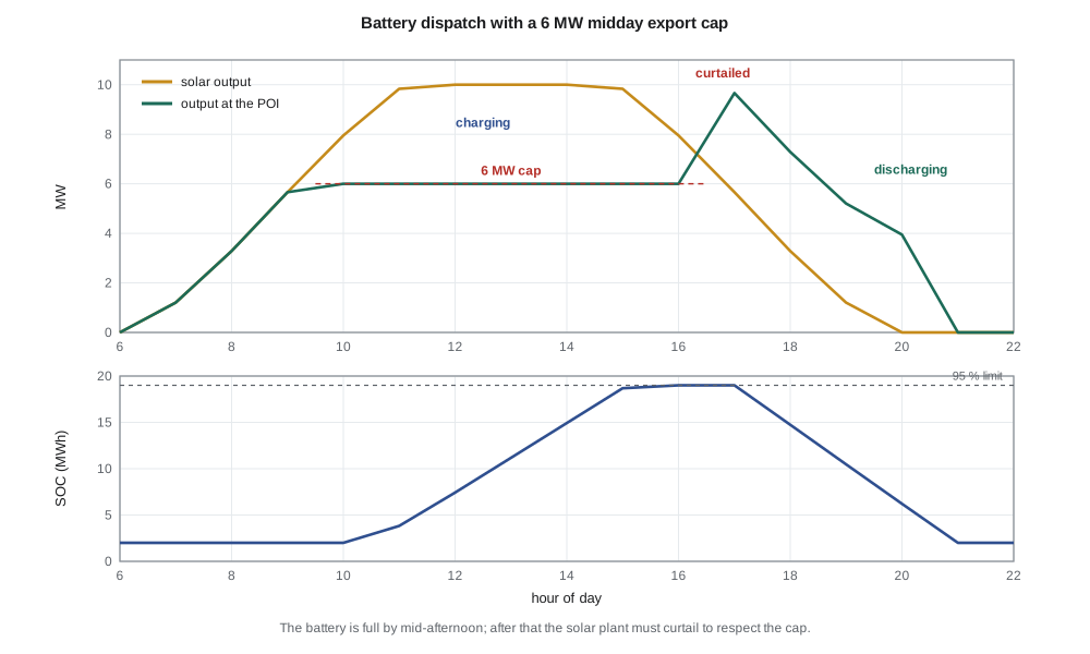
One question in Marguerite's brief is whether the battery could reduce the cost of connecting Birch Hill. If reverse flow through Lincoln Road's transformer, or voltage rise on the feeder, limits how much the plant can export at midday, the battery could absorb the excess and release it in the evening, when the substation's load is high and the feeder has spare capacity. Leo writes a simple dispatch model for a clear spring day with a 6 MW export cap at the point of interconnection during the midday hours.
import math
# Birch Hill on a clear spring day: solar output (MW AC), export cap at the POI and battery dispatch
solar = [0 if h <= 6 or h >= 20 else 10*min(1, 1.15*math.sin(math.pi*(h - 6)/14)**1.5) for h in range(24)]
CAP_EXPORT = 6.0                        # MW: export cap studied to keep T1 reverse flow acceptable
P_BAT, E_BAT, ETA = 5.0, 20.0, 0.88     # MW, MWh, round-trip efficiency (applied on charge)
soc = 2.0                               # MWh at midnight (10 %)
soc_min, soc_max = 2.0, 19.0            # keep 10-95 % of nameplate energy
log = []
for h in range(24):
    excess = max(solar[h] - CAP_EXPORT, 0)
    charge = min(excess, P_BAT, (soc_max - soc)/math.sqrt(ETA))
    discharge = 0.0
    if 17 <= h <= 21:                    # evening peak window
        discharge = min(P_BAT, (soc - soc_min)*math.sqrt(ETA), 4.0)
    soc += charge*math.sqrt(ETA) - discharge/math.sqrt(ETA)
    spill = excess - charge                # energy the plant must curtail
    log.append((h, solar[h], charge, discharge, solar[h] - charge + discharge - spill, spill, soc))
for h, s, c, d, poi, sp, e in log:
    if 7 <= h <= 21:
        print(f"{h:02d}:00 solar {s:5.2f}  charge {c:4.2f}  discharge {d:4.2f}  POI {poi:5.2f} MW  curtailed {sp:4.2f}  SOC {e:5.2f} MWh")
print(f"energy shifted {sum(x[2] for x in log):.1f} MWh in, {sum(x[3] for x in log):.1f} MWh out, "
      f"curtailed {sum(x[5] for x in log):.1f} MWh")
# Degradation and augmentation: usable energy after N years at 2 % per year
for yr in (0, 5, 10, 15):
print(f"year {yr:2d}: usable {E_BAT*(0.98**yr):5.1f} MWh, duration at 5 MW {E_BAT*(0.98**yr)/P_BAT:.1f} h")07:00 solar 1.21 charge 0.00 discharge 0.00 POI 1.21 MW curtailed 0.00 SOC 2.00 MWh 08:00 solar 3.29 charge 0.00 discharge 0.00 POI 3.29 MW curtailed 0.00 SOC 2.00 MWh 09:00 solar 5.66 charge 0.00 discharge 0.00 POI 5.66 MW curtailed 0.00 SOC 2.00 MWh 10:00 solar 7.95 charge 1.95 discharge 0.00 POI 6.00 MW curtailed 0.00 SOC 3.83 MWh 11:00 solar 9.83 charge 3.83 discharge 0.00 POI 6.00 MW curtailed 0.00 SOC 7.43 MWh 12:00 solar 10.00 charge 4.00 discharge 0.00 POI 6.00 MW curtailed 0.00 SOC 11.18 MWh 13:00 solar 10.00 charge 4.00 discharge 0.00 POI 6.00 MW curtailed 0.00 SOC 14.93 MWh 14:00 solar 10.00 charge 4.00 discharge 0.00 POI 6.00 MW curtailed 0.00 SOC 18.68 MWh 15:00 solar 9.83 charge 0.34 discharge 0.00 POI 6.00 MW curtailed 3.50 SOC 19.00 MWh 16:00 solar 7.95 charge 0.00 discharge 0.00 POI 6.00 MW curtailed 1.95 SOC 19.00 MWh 17:00 solar 5.66 charge 0.00 discharge 4.00 POI 9.66 MW curtailed 0.00 SOC 14.74 MWh 18:00 solar 3.29 charge 0.00 discharge 4.00 POI 7.29 MW curtailed 0.00 SOC 10.47 MWh 19:00 solar 1.21 charge 0.00 discharge 4.00 POI 5.21 MW curtailed 0.00 SOC 6.21 MWh 20:00 solar 0.00 charge 0.00 discharge 3.95 POI 3.95 MW curtailed 0.00 SOC 2.00 MWh 21:00 solar 0.00 charge 0.00 discharge 0.00 POI 0.00 MW curtailed 0.00 SOC 2.00 MWh energy shifted 18.1 MWh in, 15.9 MWh out, curtailed 5.4 MWh year 0: usable 20.0 MWh, duration at 5 MW 4.0 h year 5: usable 18.1 MWh, duration at 5 MW 3.6 h year 10: usable 16.3 MWh, duration at 5 MW 3.3 h year 15: usable 14.8 MWh, duration at 5 MW 3.0 h
The result is instructive. From 10:00 the battery absorbs everything above 6 MW and the plant's export stays exactly at the cap. By 15:00, however, the battery is full, and for the next two hours the solar plant must curtail about 5.4 MWh, because the battery has nowhere to put it. In the evening the battery discharges 4 MW for four hours, and the plant's output at the POI briefly rises to 9.7 MW, above the midday cap, which is acceptable because the cap applies only when the substation load is low. Over the day the battery takes in 18.1 MWh and returns 15.9 MWh, the difference being the round-trip losses.
Two lessons follow. First, a simple rule that charges only when output exceeds the cap fills the battery too early on a clear day; a forecast-based strategy that starts charging later, or charges at a lower rate spread over more hours, would avoid most of the curtailment. Second, a battery's energy, not only its power, limits what it can do for the grid: a 5 MW battery can hold a 4 MW excess for only so long before it is full. These considerations will set how much credit the utility can give the battery when it sizes upgrades in lesson 12.
Worked problem
How long can the battery hold the cap?
On a clear day the solar plant exceeds a 6 MW export cap by an average of 3.6 MW from 10:00 to 16:00. The battery starts at 2 MWh and must stay below 19 MWh, with a one-way charging efficiency of 94 %. How many hours can it absorb the excess before it is full?
Show solution
- Usable headroom: 19 − 2 = 17 MWh of stored energy.
- \[t = \dfrac{17\ \text{MWh}}{0.94 \times 3.6\ \text{MW}} \approx 5.0\ \text{h}\]
- The excess lasts 6 hours, so the battery is full about an hour before the excess ends.
Answer: About five hours; the last hour of excess must be curtailed or the charging must be spread differently.
Batteries as grid resources
Beyond shifting energy, a battery can provide almost every grid service an inverter can: reactive power for voltage control, fast frequency response, regulation that follows a control signal second by second, spinning-reserve-like capacity and, with grid-forming controls, black start and island support. Because the PCS can change from full charge to full discharge in a fraction of a second, a battery is far faster than any thermal plant. Its limitation is energy: a service that requires sustained output, such as covering a long outage, quickly exhausts it.
In the United States, FERC Order 841 required wholesale market operators to allow storage to participate in energy, capacity and ancillary service markets, and Order 2222 extended participation to aggregations of distributed resources, a topic in lesson 12. For a battery connected to Larchmont's distribution system in MISO territory, the services it could sell and the controls the utility keeps over it must be set out in the interconnection agreement.
Safety: thermal runaway and fire protection
Lithium-ion cells can fail through internal short circuits, overcharging, mechanical damage or overheating. A failing cell can enter thermal runaway, an uncontrolled reaction that releases heat and flammable gases. If the heat spreads to neighboring cells, the failure can propagate through a module and rack. Several serious battery fires and explosions in the past decade, including one in Arizona in 2019 that injured firefighters, have shaped current practice: the danger is not only fire but the build-up of flammable gas in an enclosed space.
Modern installations are designed to prevent and contain propagation. Equipment is tested to show how a failure spreads, using the UL 9540A test method, and systems are listed as complete units to UL 9540. NFPA 855, adopted through state and local fire codes, sets requirements for spacing, gas detection, deflagration venting or explosion prevention, fire suppression and emergency response plans, and Article 706 of the National Electrical Code covers the electrical installation. The local fire department must be involved in planning.
For the utility's study, safety translates into specific electrical requirements: the battery must disconnect quickly when the BMS detects a fault, the PCS must not continue exporting into a de-energized feeder, and the utility's crews need a visible, lockable disconnect at the point of interconnection, as for any generator.
Common mistakes
MistakeQuoting a battery's power rating as if it were its energy.
InsteadA 5 MW, 20 MWh battery delivers 5 MW for four hours, not 20 MW.
MistakeAssuming a battery will always be available to absorb excess solar output.
InsteadOnce full it can absorb nothing; dispatch and forecasting matter.
MistakeSumming solar and battery inverter ratings without an enforced export cap.
InsteadThe interconnection agreement must cap total export and the cap must be backed up by protection.
MistakeTreating battery fire risk as only a fire hazard.
InsteadFlammable gases from thermal runaway also create an explosion hazard in enclosures.
Summary and key terms
- A BESS consists of cells, modules and racks managed by a BMS, a bidirectional PCS, a transformer and an EMS.
- Power (MW) and energy (MWh) are separate ratings; their ratio is the duration.
- Round-trip efficiency is typically 85 to 90 % at the AC terminals; capacity fades over time, so owners plan augmentation.
- AC-coupled batteries operate independently of the solar inverters; DC-coupled batteries can capture clipped energy.
- Dispatch strategy determines how much excess solar a battery can absorb before it is full.
- Batteries can provide fast frequency response, voltage support, regulation and, with grid-forming control, black start.
- Thermal runaway can propagate and release flammable gas; testing, spacing, detection and venting address it.
- Battery management system (BMS)
- Electronics that monitor and protect cells, balance them and estimate state of charge.
- Power conversion system (PCS)
- The bidirectional inverter that connects a battery to the AC system.
- Energy management system (EMS)
- The plant controller that schedules and dispatches the battery.
- State of charge (SOC)
- Stored energy as a fraction of usable capacity.
- Round-trip efficiency
- Energy discharged divided by energy charged over a full cycle.
- Augmentation
- Adding battery capacity over the plant's life to offset degradation.
- Thermal runaway
- A self-sustaining heating reaction in a failing cell that releases heat and flammable gas.
Practice problems
Work each problem on paper first, then reveal the answer to check.
A 3 MW, 6 MWh battery has what duration and C-rate at full power?
Show answer
Two hours; 0.5C.
With 88 % round-trip efficiency, how much energy is returned from 15 MWh charged?
Show answer
About 13.2 MWh.
A 20 MWh battery loses 2 % of usable energy a year. What remains after 10 years without augmentation?
Show answer
20 × 0.98¹⁰ ≈ 16.3 MWh.
Why can a DC-coupled battery recover clipped energy and an AC-coupled one cannot?
Show answer
It sits on the DC side, before the inverter's AC limit.
Why did the simple dispatch rule cause curtailment?
Show answer
It filled the battery by mid-afternoon, leaving no room for later excess.
Name two safety measures for a battery enclosure.
Show answer
For example gas detection and deflagration venting, plus spacing and suppression.
Lesson quiz · 5 questions
Score 60% or more to complete this lesson.
Create a free account to save your progress, take quizzes and earn a certificate.