
ELE-490 · Lesson 4 of 12 · 21 min
Wind turbine generators and wind plants
Birch Hill is a solar and storage project, but the Larchmont system already has wind. Hollis Ridge Wind, twelve 2.5 MW turbines on a ridge north of the Hollis substation, has fed the 138 kV system for a decade. Its owner has asked whether the plant's reactive power controls could help with voltage on the Lincoln Road side, and Marguerite sends Leo along with Ravi Bhatt to a meeting at the plant. \"You'll understand our network better once you've seen how a wind plant behaves,\" she says. This lesson covers the electrical side of wind generation: the four types of wind turbine generator, how a doubly fed induction generator divides its power, how wind plants are collected and controlled, and what they do during grid disturbances.
From wind to the generator shaft
A wind turbine's rotor extracts kinetic energy from the air passing through its swept area. The power available rises with the cube of wind speed, so a turbine's output climbs steeply between its cut-in speed, typically about 3 m/s, and its rated speed, typically about 11 to 13 m/s. Above rated speed the blades pitch to spill excess power and hold output at rating, and above the cut-out speed, around 25 m/s, the turbine shuts down to protect itself. The energy-conversion course derived these relationships and the theoretical Betz limit; here the interest is in the electrical machine at the other end of the shaft.
The rotor turns slowly, perhaps 10 to 20 revolutions per minute for a multi-megawatt turbine. Either a gearbox raises the speed to drive a conventional generator at around 1000 to 1500 rpm, or a large multipole direct-drive generator turns at rotor speed. Either way, the generator's speed varies with the wind, while the grid frequency stays fixed at 60 Hz. How the turbine reconciles a variable shaft speed with a fixed grid frequency is what distinguishes the four turbine types.
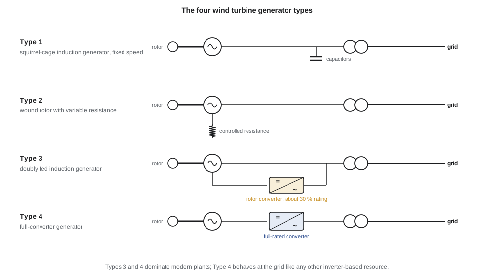
Four turbine types
Type 1 turbines use a squirrel-cage induction generator connected directly to the grid. The generator's speed can vary only by its slip of a percent or two, so the rotor turns at nearly constant speed. The machine absorbs reactive power, which is supplied by switched capacitor banks, and it behaves during faults like an induction motor running backwards, contributing a short burst of fault current. Type 1 turbines were common in early wind farms but are no longer built for utility plants.
Type 2 turbines use a wound-rotor induction generator with external rotor resistance controlled by power electronics. Adding resistance lets the slip vary by perhaps 10 %, which smooths gusts, but the energy dissipated in the resistors is lost. Type 2 machines also absorb reactive power and are now rare.
Type 3 turbines use a doubly fed induction generator (DFIG). The stator connects directly to the grid, while the rotor windings connect through slip rings to a back-to-back converter that is in turn connected to the grid. By controlling the frequency, magnitude and phase of the rotor currents, the converter lets the machine run over a speed range of roughly ±30 % around synchronous speed, controls real and reactive power independently and recovers the slip power that a Type 2 machine would waste. Type 3 turbines have been the most common type in North American fleets for many years.
Type 4 turbines connect the generator entirely through a full-rated back-to-back converter. The generator may be a permanent-magnet synchronous machine, a wound-field synchronous machine or an induction machine, and it can run at any speed, because the converter decouples it completely from the grid. To the grid a Type 4 turbine looks just like a solar or battery inverter: an inverter-based resource whose behavior is defined by its grid-side converter controls. Hollis Ridge uses Type 3 machines; many newer plants use Type 4.
How a doubly fed machine shares its power
In a DFIG, the stator always runs at grid frequency, and the rotor currents supply the difference between the stator field's speed and the rotor's mechanical speed. The power that flows through the rotor converter is approximately the slip times the stator power. Below synchronous speed (positive slip), the converter draws power from the grid to supply the rotor; above synchronous speed (negative slip), the rotor delivers power through the converter to the grid. Because the slip range is only about ±30 %, the converter needs to handle only about a third of the turbine's rating, which was the main economic advantage of Type 3 designs.
import math
# 1. Doubly fed induction generator: how power splits between stator and rotor converter
f, poles = 60.0, 6
ns = 120*f/poles                       # synchronous speed of the generator, rpm
for n in (840, 1000, 1200, 1320):      # generator speed range, rpm
    s = (ns - n)/ns                    # slip: negative above synchronous speed
    p_mech = 2.5*(n/1320)**3           # MW, rough cubic speed-power relation in the variable-speed range
    p_stator = p_mech/(1 - s)          # stator power
    p_rotor = -s*p_stator + 0.0            # power delivered through the rotor converter (+ = to grid)
    print(f"n {n:4d} rpm, slip {s:+.2f}: mechanical {p_mech:4.2f} MW, stator {p_stator:4.2f} MW, "
          f"rotor converter {p_rotor:+5.2f} MW ({abs(p_rotor)/2.5*100:3.0f} % of rating)")
# 2. Power curve and Weibull wind speed distribution at hub height
def power(v):                          # 2.5 MW turbine, cut-in 3, rated 12, cut-out 25 m/s
    if v < 3 or v >= 25: return 0.0
    if v >= 12: return 2.5
    return 2.5*(v**3 - 27)/(12**3 - 27)
k, c = 2.1, 7.6                        # Weibull shape and scale, m/s
pdf = lambda v: (k/c)*(v/c)**(k - 1)*math.exp(-(v/c)**k)
dv = 0.1; e = sum(power(i*dv)*pdf(i*dv)*dv for i in range(1, 300))*8760
print(f"Annual energy per turbine {e:,.0f} MWh, capacity factor {e/(2.5*8760)*100:.1f} %")
# 3. Plant reactive capability: 12 turbines with 0.95 pf capability each, plus collector charging
n_wt = 12; p = 2.5*n_wt
q_wt = n_wt*2.5*math.tan(math.acos(0.95))
print(f"Plant {p:.0f} MW: turbines can supply +/-{q_wt:.1f} Mvar at full output")n 840 rpm, slip +0.30: mechanical 0.64 MW, stator 0.92 MW, rotor converter -0.28 MW ( 11 % of rating) n 1000 rpm, slip +0.17: mechanical 1.09 MW, stator 1.30 MW, rotor converter -0.22 MW ( 9 % of rating) n 1200 rpm, slip +0.00: mechanical 1.88 MW, stator 1.88 MW, rotor converter +0.00 MW ( 0 % of rating) n 1320 rpm, slip -0.10: mechanical 2.50 MW, stator 2.27 MW, rotor converter +0.23 MW ( 9 % of rating) Annual energy per turbine 5,813 MWh, capacity factor 26.5 % Plant 30 MW: turbines can supply +/-9.9 Mvar at full output
The program follows a 2.5 MW, six-pole DFIG, whose synchronous speed is 1200 rpm, across its speed range. At 840 rpm the slip is +0.30: the shaft delivers 0.64 MW, the stator sends 0.92 MW to the grid and the rotor converter draws 0.28 MW back from it. At synchronous speed no power flows through the rotor. At 1320 rpm and full output the slip is −0.10: the stator delivers 2.27 MW and the rotor converter adds 0.23 MW. Across the whole range the converter never handles more than about 11 % of the rating in this example, and real designs allow margin for reactive power and fault ride-through on top of that.
The program also estimates the annual energy of one turbine from its power curve and a Weibull distribution of wind speed at hub height, a calculation covered in more depth in the energy-conversion course. With a shape factor of 2.1 and a scale of 7.6 m/s, each turbine produces about 5,800 MWh a year, a capacity factor of about 26 %. Hollis Ridge's twelve turbines therefore deliver about 70 GWh a year, far more energy than Birch Hill's solar plant, but spread across all hours, including winter nights.
Worked problem
Converter power in a DFIG
A DFIG with a synchronous speed of 1500 rpm runs at 1800 rpm and its stator delivers 2.0 MW. Estimate the slip and the power flowing through the rotor converter.
Show solution
- \[s = \dfrac{n_s - n}{n_s} = \dfrac{1500 - 1800}{1500} = -0.20\]
- \[P_r \approx -s\,P_s = 0.20 \times 2.0\ \text{MW} = 0.40\ \text{MW}\]
- The negative slip means power flows from the rotor through the converter to the grid.
Answer: Slip −0.20; about 0.4 MW flows out through the rotor converter, so the turbine delivers about 2.4 MW in total.
The wind plant as a single resource
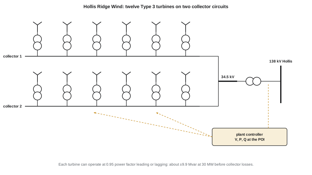
A wind plant collects its turbines through a medium-voltage collector system, usually at 34.5 kV in the United States and at 34.5 kV or 25 kV in Canada. Each turbine has a pad-mounted or nacelle step-up transformer from its generator voltage, typically 690 V. Underground collector cables run along strings of turbines to a plant substation, where a main power transformer steps up to transmission voltage. At Hollis Ridge, two collector circuits of six turbines each feed a 34.5/138 kV transformer.
A plant controller at the substation measures voltage, real power and reactive power at the point of interconnection and sends setpoints to every turbine. It regulates voltage or reactive power at the POI, limits real power when the system operator curtails the plant, limits ramp rates and implements frequency response. Because a wind plant's collector system can be tens of kilometers long, the reactive power that the turbines produce is partly consumed or supplemented by the collector cables and transformers, and the plant controller compensates for that. Many plants also have switched capacitor banks or a static compensator to extend their reactive range.
Hollis Ridge's turbines can each operate at a power factor of 0.95 leading or lagging at full output, so the plant can deliver or absorb about 9.9 Mvar at 30 MW. That is what makes the owner's offer interesting: the plant could regulate voltage on the 138 kV bus at Hollis, which in turn influences Lincoln Road. Ravi points out that the utility would need to coordinate the plant's voltage control with Lincoln Road's tap changer and capacitor bank, or the devices could fight each other. Lesson 8 returns to that coordination problem.
Wind plants during faults and frequency events
Type 3 and Type 4 turbines must ride through grid faults, and each type faces its own difficulty. In a DFIG, a sudden voltage dip on the stator induces large currents and voltages in the rotor circuit, which could destroy the rotor converter. Designs protect it with a crowbar, a circuit that shorts the rotor windings during severe faults, or with a DC-link chopper that dumps excess energy into a resistor. While the crowbar is active, the machine briefly behaves like a squirrel-cage induction generator, absorbing reactive power and contributing a short burst of fault current. A Type 4 turbine's grid-side converter limits fault current like any other inverter, while a braking chopper absorbs the power the generator keeps producing.
Wind turbines can also provide frequency response. Because the rotor stores kinetic energy, a turbine can be programmed to release some of it briefly when frequency falls, a function known as synthetic or emulated inertia. Unlike a synchronous generator's inertial response, it must be deliberately designed in, and after releasing energy the rotor slows and must recover, which can cause a second dip in output. For sustained upward response a wind plant must operate below its available power, which costs energy, so most plants provide only downward response, reducing output when frequency rises. Lesson 11 compares these responses with those of batteries and synchronous machines.
Ravi and Leo leave Hollis Ridge with a list of questions for the planning group: whether the plant's voltage control could be set to support Lincoln Road during the midday reverse-flow periods, and how its control mode should change if Birch Hill connects. The wind plant and the solar-plus-storage plant will share the same transmission corridor, and the study must consider them together.
Common mistakes
MistakeAssuming a DFIG's rotor converter handles the full turbine rating.
InsteadIt handles roughly the slip power, about a third of the rating or less.
MistakeTreating all wind turbines as identical inverter-based resources.
InsteadType 3 machines have a directly connected stator and behave differently from full-converter Type 4 machines during faults.
MistakeExpecting synthetic inertia to behave like synchronous inertia.
InsteadIt must be programmed, is limited, and the rotor must recover energy afterwards.
MistakeIgnoring the collector system when checking a plant's reactive capability at the POI.
InsteadCables and transformers consume or supply reactive power between the turbines and the POI.
Summary and key terms
- Wind power rises with the cube of wind speed between cut-in and rated speed; pitch control limits output above rated.
- Type 1 and 2 turbines use induction generators with little or no speed range and absorb reactive power.
- Type 3 doubly fed induction generators pass about the slip power through a partially rated rotor converter.
- Type 4 turbines connect through a full-rated converter and behave like other inverter-based resources.
- Plant controllers coordinate turbines to regulate voltage, curtail output, limit ramps and respond to frequency.
- DFIGs protect their rotor converters during faults with crowbars or DC choppers.
- Wind plants can provide synthetic inertia and downward frequency response; upward response needs curtailed operation.
- Doubly fed induction generator (DFIG)
- An induction generator whose rotor is supplied through a back-to-back converter, allowing variable speed.
- Slip
- The difference between synchronous and rotor speed divided by synchronous speed.
- Full-converter turbine
- A Type 4 turbine connected entirely through a back-to-back converter.
- Collector system
- The medium-voltage network that gathers turbine output to the plant substation.
- Plant controller
- The central controller that sets turbine setpoints to meet requirements at the POI.
- Crowbar
- A circuit that shorts a DFIG's rotor windings to protect the converter during severe faults.
- Synthetic inertia
- A programmed release of rotor kinetic energy in response to falling frequency.
Practice problems
Work each problem on paper first, then reveal the answer to check.
A six-pole DFIG on a 60 Hz grid turns at 1080 rpm. What is its slip?
Show answer
(1200 − 1080)/1200 = +0.10.
At that slip, with stator power 1.5 MW, how much power flows through the rotor converter, and in which direction?
Show answer
About 0.15 MW drawn from the grid into the rotor.
Why are Type 4 turbines similar to solar plants from the grid's viewpoint?
Show answer
Both connect entirely through inverters whose controls define their behavior.
A 40 MW plant has turbines capable of 0.95 power factor. What reactive power can they supply at full output?
Show answer
40 × tan(acos 0.95) ≈ 13.1 Mvar.
Why does synthetic inertia cause a second dip in output?
Show answer
The rotor slows while releasing energy and must be re-accelerated.
Why must a wind plant be curtailed to provide upward frequency response?
Show answer
It needs headroom below its available power to increase output.
Lesson quiz · 5 questions
Score 60% or more to complete this lesson.
Create a free account to save your progress, take quizzes and earn a certificate.