
ELE-490 · Lesson 11 of 12 · 21 min
Frequency response, inertia and system stability
Frequency is the one quantity shared by every generator and load in an interconnection. When a large generator trips, frequency falls everywhere at once, and what happens in the next few seconds depends on how much kinetic energy is stored in spinning machines, how quickly other resources raise their output and how much load responds. Birch Hill on its own is far too small to affect frequency in the Eastern Interconnection, which both New Brunswick and Wisconsin belong to. But it is one of thousands of similar plants, and their combined behavior now shapes how the bulk system responds. This lesson looks at frequency dynamics, at why inverter-based resources change them and at what Birch Hill's battery can contribute.
The first seconds after a generator trips
Before a disturbance, generation equals load plus losses, and frequency is steady at 60 Hz. When a generator trips, the remaining generators must supply the missing power instantly, and the only immediate source is the kinetic energy stored in their rotating masses. As they release it they slow down, and frequency falls. The swing equation for the system as a whole relates the rate of change of frequency (RoCoF) to the power imbalance: df/dt = f₀ ΔP / (2 H S), where ΔP is the imbalance, S the total rating of the online synchronous machines and H their inertia constant, the stored kinetic energy in seconds of rated power. Typical H values for synchronous generators range from about 2 to 9 seconds.
Within the first second or two, load also helps a little: motors slow with frequency and draw less power, an effect called load damping. After a short delay, governors on synchronous generators begin to open valves or gates, raising mechanical power. Frequency falls until the combined response matches the lost power. The lowest point is the frequency nadir. Governors then restore frequency to a steady level a few tenths of a hertz below 60 Hz, set by their droop characteristics, and over several minutes automatic generation control brings it back to 60 Hz and restores scheduled flows.
Why inverter-based resources change the picture
Wind, solar and battery plants connected through grid-following inverters contribute no inherent inertia: their output does not change by itself when frequency changes, because the inverter's control regulates current regardless of the grid's rotational speed. As they displace synchronous generators, the total stored kinetic energy falls, so the same generator trip produces a steeper RoCoF and, unless other resources respond faster, a deeper nadir. High RoCoF can also trip generators and loads whose protection uses rate-of-change-of-frequency relays, and a deep nadir can reach the first stages of underfrequency load shedding (UFLS), which automatically disconnect blocks of customer load to stop the decline.
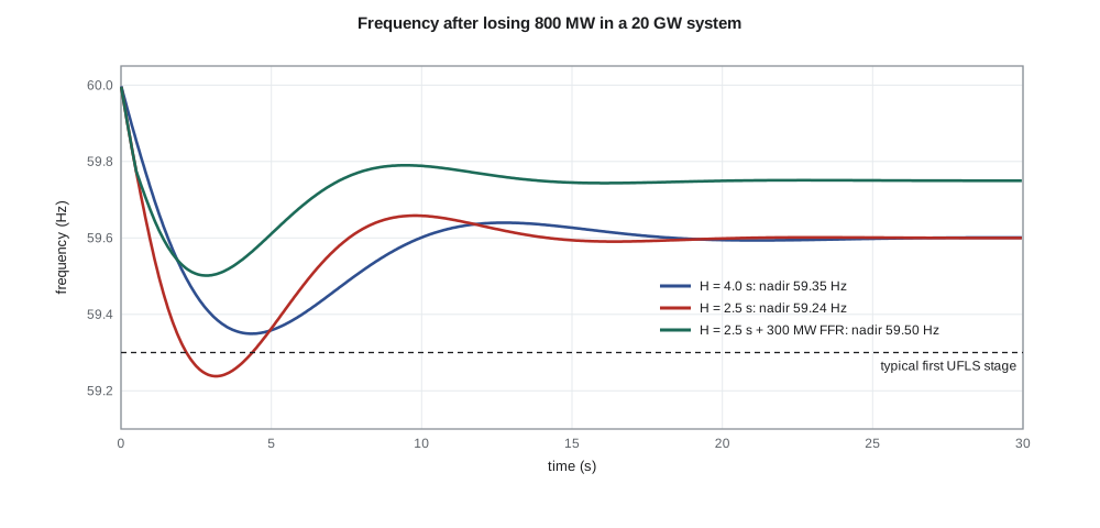
Leo models a generic 20 GW system, comparable to a smaller interconnection or a region that has separated from the rest of the grid, and trips an 800 MW generator. Governors respond with a one-second delay and a four-second lag, and load damping is 1.5 % of load per 1 % of frequency. He then reduces the inertia constant from 4 to 2.5 seconds, as if a large share of synchronous generation had been replaced by inverter-based plants, and adds a block of fast frequency response from batteries.
import math
# Single-area frequency model after losing a large generator
f0 = 60.0
def event(S_sys, H, loss, ffr_mw=0.0, ffr_delay=0.5, gov_share=1.0, label=''):
    """S_sys MW online, H s inertia, loss MW; governors respond with a 4 s lag after a 1 s delay."""
    D = 1.5*S_sys/100/(0.01*f0)         # load damping: 1.5 % of load per 1 % frequency change, MW/Hz
    dt, f, t, nadir, tn, p_gov = 0.01, f0, 0.0, f0, 0.0, 0.0
    rocof = None
    while t < 30:
        p_ffr = ffr_mw if t >= ffr_delay else 0.0
        target = min(gov_share*1500*(f0 - f), 1500) if t > 1.0 else 0.0     # governor droop response, headroom 1500 MW
        p_gov += (target - p_gov)*dt/4.0
        dp = -loss + p_gov + p_ffr + D*(f0 - f)
        dfdt = dp*f0/(2*H*S_sys)
        if rocof is None: rocof = dfdt
        f += dfdt*dt; t += dt
        if f < nadir: nadir, tn = f, t
    print(f"{label:34s} RoCoF {rocof:+.3f} Hz/s, nadir {nadir:.3f} Hz at {tn:4.1f} s, settles near {f:.3f} Hz")
event(20000, 4.0, 800, label='H = 4.0 s, no fast response')
event(20000, 2.5, 800, label='H = 2.5 s (many IBR), no FFR')
event(20000, 2.5, 800, ffr_mw=300, label='H = 2.5 s + 300 MW FFR at 0.5 s')
event(20000, 2.5, 800, ffr_mw=300, ffr_delay=0.2, label='H = 2.5 s + 300 MW FFR at 0.2 s')
# IEEE 1547-2018 default frequency-droop for Birch Hill's battery (5 % droop, 0.036 Hz deadband)
P_RATED = 5.0
for f in (59.95, 59.8, 59.5):
    dp = max(0.0, (60 - 0.036 - f)/(60*0.05))*P_RATED
print(f"battery at {f:.2f} Hz: increases output by {dp:4.2f} MW")H = 4.0 s, no fast response RoCoF -0.300 Hz/s, nadir 59.349 Hz at 4.3 s, settles near 59.601 Hz H = 2.5 s (many IBR), no FFR RoCoF -0.480 Hz/s, nadir 59.238 Hz at 3.2 s, settles near 59.600 Hz H = 2.5 s + 300 MW FFR at 0.5 s RoCoF -0.480 Hz/s, nadir 59.502 Hz at 2.8 s, settles near 59.750 Hz H = 2.5 s + 300 MW FFR at 0.2 s RoCoF -0.480 Hz/s, nadir 59.516 Hz at 3.0 s, settles near 59.750 Hz battery at 59.95 Hz: increases output by 0.02 MW battery at 59.80 Hz: increases output by 0.27 MW battery at 59.50 Hz: increases output by 0.77 MW
With H = 4 s, the initial RoCoF is −0.30 Hz/s and the nadir is 59.35 Hz after about four seconds. Cutting inertia to 2.5 s steepens the RoCoF to −0.48 Hz/s and deepens the nadir to 59.24 Hz, below a typical first UFLS stage. Adding 300 MW of fast frequency response, delivered half a second after the event, lifts the nadir to 59.50 Hz, better than the high-inertia case, and leaves frequency settling higher. Delivering it at 0.2 s instead of 0.5 s helps only a little more, because by then the rotating mass has already slowed the initial fall. The essential point is that a modest amount of very fast response can make up for a large loss of inertia.
Inertia, fast frequency response and primary response
Three kinds of response are often distinguished. Inertial response is the immediate, physics-driven release of kinetic energy from synchronous machines and, with appropriate controls, from wind turbine rotors or grid-forming inverters emulating inertia. Fast frequency response (FFR) is a deliberate, rapid change in power from inverter-based resources or loads, triggered by a frequency threshold or proportional to RoCoF, delivered within a fraction of a second to a couple of seconds. Primary frequency response is the proportional response of governors and their inverter equivalents to the frequency deviation, sustained until secondary control takes over.
Batteries are ideal for the second and third. They can move from idle to full discharge in well under a second and hold their output for as long as their energy lasts. Solar and wind plants can respond downward easily by curtailing and can respond upward only if they operate with headroom below their available power. Grid-forming inverters provide something closer to true inertial response, because their voltage source responds to the phase shift caused by a frequency change within milliseconds, before any measurement or threshold is crossed.
IEEE 1547-2018 requires distributed resources to provide a frequency-droop response: to reduce output when frequency rises above a deadband, and, where they have headroom, to increase output when it falls. The default settings are a deadband of 0.036 Hz and a droop of 5 %, meaning full rated change in output for a 5 % change in frequency, 3 Hz. The program shows what that means for Birch Hill's 5 MW battery: at 59.8 Hz it increases its output by 0.27 MW, and at 59.5 Hz by 0.77 MW. That is a small contribution from one plant, but across a fleet of many batteries it adds up, and the utility can set a steeper droop for its own resources if it wishes.
Worked problem
RoCoF from the swing equation
In a system with 15 GW of synchronous generation online and an average inertia constant of 3.5 s, a 600 MW generator trips. Estimate the initial rate of change of frequency, ignoring load damping.
Show solution
- \[\dfrac{df}{dt} = \dfrac{f_0\,\Delta P}{2 H S} = \dfrac{60 \times (-600)}{2 \times 3.5 \times 15\,000}\]
- \[\dfrac{df}{dt} \approx -0.34\ \text{Hz/s}\]
Answer: About −0.34 Hz/s at the instant after the trip.
Bulk system requirements and lessons from disturbances
Frequency response obligations for balancing areas in North America are set by NERC reliability standards, and FERC has required new generators interconnecting to the transmission system to have primary frequency response capability. System operators such as MISO translate these into plant requirements: frequency-droop response for new inverter-based resources, limits on the frequency deadband and, in some regions, procurement of fast frequency response or grid-forming capability. Wisconsin, being part of a very large interconnection, sees small frequency deviations in normal operation, but the same plants must respond correctly during rare large events or islanding.
Analyses of several disturbances in North America have shaped current requirements. In the 2016 Blue Cut fire event in California, a transmission fault caused about 1,200 MW of solar generation to reduce output or disconnect, because inverters misread the fault as a frequency excursion or ceased current during the voltage dip. Later events in Texas, among others, showed solar plants tripping on overly sensitive protection settings, PLL errors and AC overvoltages after faults cleared. Each investigation, published by NERC and the system operators, added items to the list of required inverter behaviors: ride-through, correct frequency measurement, limited momentary cessation and validated models.
Models and model validation
Every one of these issues depends on having accurate models of how inverter-based plants respond. Planners need positive-sequence models for wide-area stability studies, which must be validated against measurements from actual disturbances or staged tests, and increasingly EMT models for detailed studies of weak areas. NERC standards require generator owners to provide and verify their models, and following FERC Order 901 those requirements are being extended specifically to inverter-based resources. For distributed resources such as Birch Hill, the transmission operator needs aggregate models of all the DER behind each substation, including the share that would trip, cease current or ride through for each kind of disturbance.
Leo adds two requirements to the study's list. Birch Hill must provide a validated plant model in the formats Larchmont's planning tools use, with the parameters matching the settings actually installed. And the plant's event recorder must capture high-resolution voltage, current and frequency data during disturbances, so that Larchmont can confirm after each event that the plant behaved as the model predicts.
Other forms of stability
Frequency is only one aspect of stability. Rotor-angle stability concerns whether synchronous generators stay in step after a fault, and it can improve or worsen as inverter-based resources displace synchronous machines, depending on location and control. Voltage stability concerns whether the system can supply reactive power to hold voltage up under heavy load; inverters with reactive capability help, but their current limits matter during deep sags. Converter-driven stability, a newer category, covers oscillations and instabilities arising from interactions between inverter controls and the network, such as those in weak grids or near series capacitors, which typically need EMT studies to analyze. Birch Hill is too small and too well connected to raise these issues by itself, but Leo's report notes them so that the planning group can track the aggregate effect as more plants connect.
Common mistakes
MistakeAssuming solar and wind plants automatically help arrest a frequency decline.
InsteadGrid-following inverters have no inherent inertia and need headroom and controls to respond.
MistakeTreating inertia and fast frequency response as unrelated.
InsteadFast response can compensate for lower inertia, as long as it arrives within the first second or two.
MistakeExpecting one distributed battery to matter at interconnection scale.
InsteadIndividually small, distributed resources matter in aggregate.
MistakeUsing a plant model with default parameters.
InsteadModels must match the settings actually installed and be validated against measurements.
Summary and key terms
- After a generator trips, kinetic energy from rotating machines sets the initial RoCoF; governors then arrest and stabilize frequency.
- The swing equation gives df/dt = f₀ΔP/(2HS).
- Displacing synchronous machines with grid-following IBR reduces inertia, steepening RoCoF and deepening the nadir.
- Fast frequency response from batteries can offset reduced inertia if delivered within about a second.
- IEEE 1547-2018 sets default frequency-droop response with a 0.036 Hz deadband and 5 % droop.
- Major disturbances where inverter plants tripped or ceased current drove today's ride-through and modeling requirements.
- Validated models of plants and aggregated DER are essential for bulk system studies.
- Rate of change of frequency (RoCoF)
- The slope of frequency immediately after a power imbalance.
- Inertia constant (H)
- Stored rotating kinetic energy divided by machine rating, in seconds.
- Frequency nadir
- The lowest frequency reached after a loss of generation.
- Fast frequency response (FFR)
- Rapid power change from inverters or loads within about a second of a frequency event.
- Primary frequency response
- Proportional response of governors or their equivalents to frequency deviation.
- Underfrequency load shedding (UFLS)
- Automatic disconnection of load blocks when frequency falls below set thresholds.
- Converter-driven stability
- Stability of interactions between converter controls and the network.
Practice problems
Work each problem on paper first, then reveal the answer to check.
A 10 GW system with H = 5 s loses 500 MW. What is the initial RoCoF?
Show answer
−60 × 500/(2 × 5 × 10 000) = −0.30 Hz/s.
If H falls to 2.5 s, what is the RoCoF for the same event?
Show answer
−0.60 Hz/s.
Why did delivering fast frequency response at 0.2 s instead of 0.5 s help only slightly?
Show answer
Inertia had already slowed the initial fall; most of the benefit comes once the response arrives within the first second.
Using the default IEEE 1547 droop, how much does a 2 MW battery increase output at 59.7 Hz?
Show answer
(60 − 0.036 − 59.7)/3 × 2 ≈ 0.18 MW.
Why can a solar plant at full output not provide upward frequency response?
Show answer
It has no headroom above its available power.
What data should Birch Hill's event recorder capture?
Show answer
High-resolution voltage, current and frequency during disturbances.
Lesson quiz · 5 questions
Score 60% or more to complete this lesson.
Create a free account to save your progress, take quizzes and earn a certificate.