
DCE-210 · Lesson 9 of 12 · 36 min
Optical transport and wavelengths
Almost every bit that leaves a server rack travels part of its journey as light. Inside a data hall, light carries traffic from leaves to spines over a few hundred meters. Across a campus, it links buildings over a few kilometers. Between data centers in a metro area, between cities and under oceans, it carries terabits per second over thousands of kilometers. Fiber optics is the physical layer of the modern internet, and it is the part of networking that data center engineers design most directly: the fiber types, the cable plant, the connectors, the loss budgets and the rooms for optical equipment.
This chapter explains how optical fiber works, the two main fiber types and when each is used, how transceivers are named and what their reach limits are, how to calculate a loss budget, and how dense wavelength division multiplexing (DWDM) packs dozens of independent channels into one fiber for long-distance and data center interconnect links.
How optical fiber works
An optical fiber is a strand of ultra-pure glass about the thickness of a human hair: 125 µm in diameter. It has two parts: a central core and a surrounding cladding, made of glass with a slightly lower refractive index. Light launched into the core strikes the core-cladding boundary at a shallow angle and is reflected back by total internal reflection, so it stays trapped in the core and follows the fiber around gentle bends. A plastic coating, 250 µm in diameter (sometimes 200 µm in high-density cables), protects the glass, and cables add buffer tubes, strength members and an outer jacket.
Glass absorbs and scatters a little light. The loss is measured in decibels per kilometer (dB/km) and depends strongly on wavelength. Modern single-mode fiber loses roughly 0.35 dB/km at 1310 nm and about 0.2 dB/km at 1550 nm, which means half the light remains after about 15 km at 1550 nm. That astonishing transparency is what makes long-distance optical communication possible.
Light in glass travels slower than in a vacuum by a factor equal to the refractive index, about 1.47 for the core of standard fiber. That gives the figure from Lesson 7: about 204,000 km/s, or 4.9 µs per kilometer.
Decibels in optics
Optical power is expressed in dBm, decibels relative to one milliwatt:
So 1 mW is 0 dBm, 2 mW is about +3 dBm, 0.5 mW is about −3 dBm and 0.1 mW is −10 dBm. Losses are expressed in dB. The advantage is that losses simply add: the power at the receiver in dBm is the transmitter power in dBm minus the sum of all the losses in dB along the way. A loss of 3 dB halves the power; 10 dB leaves one tenth; 20 dB leaves one hundredth.
Single-mode and multimode fiber
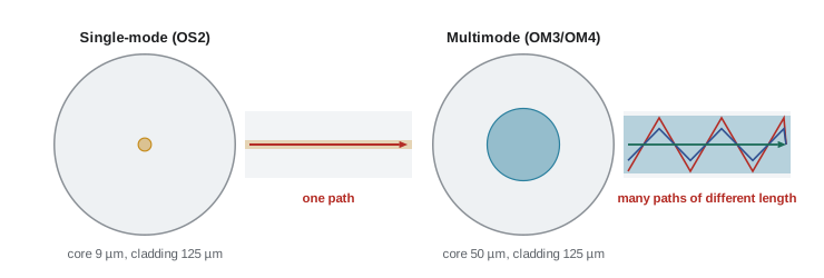
The core diameter decides how many paths, or modes, light can take through the fiber.
- Single-mode fiber (SMF) has a tiny core, about 9 µm across. Only one mode propagates, so pulses do not spread out from different path lengths. Single-mode fiber carries signals for tens of kilometers without amplification and thousands with it. The standard grade for data centers and outside plant is OS2 (ITU-T G.652.D), often with bend-insensitive versions (G.657.A1) for tight routing. Its jacket is usually yellow.
- Multimode fiber (MMF) has a larger core, 50 µm in modern grades. Many modes propagate, each taking a slightly different path, so a short pulse spreads out over distance (modal dispersion). This limits reach to a few hundred meters at high speeds. Multimode grades are named OM3, OM4 and OM5, with increasing bandwidth; OM3 jackets are usually aqua, OM4 aqua or violet (erika violet), and OM5 lime green. Older OM1 and OM2 fibers are obsolete for data centers.
Why use multimode at all? Historically, multimode optics used cheap vertical-cavity surface-emitting lasers (VCSELs) at 850 nm and were much less expensive than single-mode optics, while the larger core made alignment easier. For links under about 100 m, multimode was the economical choice. As speeds have risen and single-mode optics have become cheaper through enormous hyperscale volumes, the balance has shifted. Many new hyperscale and AI facilities use single-mode fiber for almost everything beyond the rack, because single-mode reach easily covers any hall and the same fiber will support future speeds. Enterprise and colocation facilities still use a lot of OM4 multimode for short links.
Transceivers and their names
Lesson 1 introduced pluggable transceivers. Their IEEE names describe what they do: speed, signaling, reach and lanes. For example, in 400GBASE-DR4, "400G" is the speed, "BASE" means baseband signaling, "DR" means 500 m reach on single-mode fiber, and "4" means four parallel lanes, each on its own fiber pair. The common reach codes are SR (short reach, multimode), DR (500 m, single-mode, parallel fibers), FR (2 km, single-mode), LR (6 to 10 km) and ER (30 to 40 km).
| Optic | Lanes | Fiber and connector | Reach |
|---|---|---|---|
| 100GBASE-SR4 | 4 × 25 Gb/s, 850 nm | Multimode, MPO-12 (8 fibers used) | 70 m OM3, 100 m OM4 |
| 400GBASE-SR8 | 8 × 50 Gb/s, 850 nm | Multimode, MPO-16 (16 fibers) | 70 m OM3, 100 m OM4 |
| 400GBASE-DR4 | 4 × 100 Gb/s, 1310 nm | Single-mode, MPO-12 (8 fibers used) | 500 m |
| 400GBASE-FR4 | 4 wavelengths × 100 Gb/s | Single-mode, duplex LC (2 fibers) | 2 km |
| 100GBASE-LR4 | 4 wavelengths × 25 Gb/s | Single-mode, duplex LC | 10 km |
| 800GBASE-DR8 | 8 × 100 Gb/s, 1310 nm | Single-mode, MPO-16 (16 fibers) | 500 m |
| 400ZR (coherent) | 1 DWDM wavelength | Single-mode, duplex LC | About 120 km amplified |
There are two ways to build a fast optic from slower lanes. Parallel optics (SR4, SR8, DR4, DR8) send each lane on its own fiber, so a 400GBASE-DR4 link uses eight fibers: four to transmit and four to receive. Wavelength-multiplexed optics (FR4, LR4) put each lane on a different wavelength and combine them onto one fiber, so the link needs only two fibers. Parallel optics are cheaper per module and can be broken out into separate lower-speed links; multiplexed optics save fiber, which matters over longer distances. The choice decides the fiber count of the whole cable plant, so it must be agreed with the network architect before the cabling is designed.
Connectors
Duplex links use LC connectors, which are small push-latch connectors holding one fiber each, mounted in pairs. Parallel optics use MPO (multi-fiber push-on) connectors holding 8, 12, 16 or 24 fibers in a single rectangular ferrule. Very small form factor connectors (such as SN, MDC and CS) pack two fibers into a smaller footprint so that more links fit in a patch panel or an 800G transceiver can carry two duplex links.
Single-mode connectors come with two end-face polishes. UPC (ultra physical contact) connectors have a domed end face and are usually blue. APC (angled physical contact) connectors are polished at 8° so that reflected light leaves the core, and they are green. They must never be mated with each other: the gap damages both and causes high loss. Many modern single-mode optics, including MPO-based DR4, use APC connectors.
Contamination is the leading cause of optical link problems. A speck of dust a few micrometers across on a single-mode core can block much of the light or scratch the end face permanently when the connector is mated. The rule in every data center is "inspect before you connect": every connector end face is examined with a fiber microscope and cleaned if necessary before it is plugged in, using standard pass/fail criteria (IEC 61300-3-35).
Loss budgets
Every optic has a power budget: the maximum loss the link between its transmitter and receiver can have while still working within its specified error rate. IEEE specifies this as the maximum channel insertion loss. For example, 100GBASE-SR4 allows 1.9 dB over OM4, and 100GBASE-LR4 allows 6.3 dB. A designer must check that the loss of each planned link is below the budget, with some margin for aging, repairs and future patching.
The loss of a link is the sum of three parts:
where \(\alpha\) is the fiber attenuation in dB/km, \(L\) the length in km, \(n_c\) and \(L_c\) the number of mated connector pairs and the loss of each, and \(n_s\) and \(L_s\) the number of splices and the loss of each. Typical design values are about 3.0 dB/km for multimode fiber at 850 nm, 0.35 to 0.5 dB/km for single-mode fiber at 1310 nm, 0.15 to 0.5 dB per mated connector pair depending on quality (MPO connectors are higher than LC), and 0.1 dB per fusion splice.
Worked problem
Short multimode link
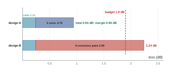
A 100GBASE-SR4 link over OM4 has a channel budget of 1.9 dB. The run is 80 m with two MPO connector pairs (one patch panel at each end) at 0.35 dB each. Does it work? What if the link passes through two more patch panels (four connector pairs in total) with standard connectors at 0.5 dB each?
Show solution
- Fiber loss: \(3.0 \times 0.080 = 0.24\) dB.
- Two low-loss connector pairs: \(2 \times 0.35 = 0.70\) dB.
- Total: \(0.24 + 0.70 = 0.94\) dB, leaving \(1.9 - 0.94 = 0.96\) dB of margin. It works.
- With four standard pairs: \(4 \times 0.5 = 2.0\) dB of connector loss.
- Total: \(0.24 + 2.0 = 2.24\) dB, which exceeds 1.9 dB. It fails.
Answer: The first design works with almost 1 dB of margin; the second does not. On short links, the number and quality of connectors matter far more than the fiber length, which is why high-speed designs limit patch points and specify low-loss connectors.
Worked problem
Single-mode campus link
A 100GBASE-LR4 link (budget 6.3 dB) connects two buildings over 8 km of single-mode fiber at 0.35 dB/km, with two connector pairs at 0.5 dB and four fusion splices at 0.1 dB. The transmitter launches −1 dBm. What is the link loss, the margin, and the power at the receiver in dBm and milliwatts?
Show solution
- Fiber: \(0.35 \times 8 = 2.8\) dB.
- Connectors: \(2 \times 0.5 = 1.0\) dB. Splices: \(4 \times 0.1 = 0.4\) dB.
- Total: \(2.8 + 1.0 + 0.4 = 4.2\) dB.
- Margin: \(6.3 - 4.2 = 2.1\) dB.
- Received power: \(-1 - 4.2 = -5.2\) dBm, which is \(10^{-5.2/10} = 0.30\) mW.
Answer: Link loss 4.2 dB, margin 2.1 dB, and about −5.2 dBm (0.30 mW) at the receiver. A margin of 2 to 3 dB allows for future splice repairs after a cable cut.
After installation, every link is tested. A light source and power meter measure total loss against the design. An OTDR (optical time-domain reflectometer) sends pulses down the fiber and measures reflections over time, producing a trace that shows the location and loss of each connector, splice and fault; it is the tool that tells a repair crew exactly where a cable has been cut.
Dense wavelength division multiplexing
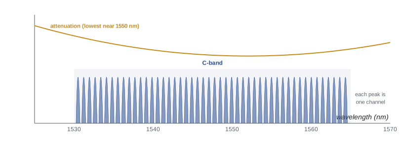
One fiber can carry many signals at once if each uses a different wavelength, just as many radio stations share the air on different frequencies. This is wavelength division multiplexing (WDM). Coarse WDM (CWDM), used inside FR4 and LR4 optics, places a few wavelengths 20 nm apart. Dense WDM (DWDM) packs dozens of channels closely together in the C-band, the range around 1530 to 1565 nm where fiber loss is lowest and optical amplifiers work best.
DWDM channels are placed on a grid of frequencies defined by ITU-T Recommendation G.694.1, anchored at 193.1 THz. The wavelength of a channel follows from \(\lambda = c/f\): 193.1 THz corresponds to 1552.52 nm. Older systems used fixed 100 GHz or 50 GHz spacing. Modern systems use a flexible grid in 12.5 GHz slices, giving each channel as much spectrum as its data rate needs, for example 75 GHz for a 400 Gb/s channel.
Worked problem
Capacity of one fiber pair
A DWDM system uses about 4.8 THz of C-band spectrum. Each 400 Gb/s channel needs 75 GHz. How many channels fit and what is the total capacity of one fiber pair (one fiber each way)?
Show solution
- Channels: \(4800 / 75 = 64\).
- Capacity: \(64 \times 400 = 25{,}600\) Gb/s = 25.6 Tb/s in each direction.
Answer: 64 channels and 25.6 Tb/s per fiber pair. Newer systems run 800 Gb/s to 1.6 Tb/s per channel and add the L-band (about 1570 to 1610 nm), roughly doubling the spectrum, for well over 50 Tb/s per pair.
Coherent optics and amplifiers
High-speed long-distance channels use coherent optics. Instead of just switching light on and off or between intensity levels, a coherent transmitter encodes data in the amplitude and phase of the light and in both polarizations, and the receiver mixes the incoming signal with a local laser and uses a powerful digital signal processor (DSP) to recover it. The DSP also undoes chromatic dispersion, the spreading of pulses because different wavelengths travel at slightly different speeds (about 17 ps per nm per km in standard fiber at 1550 nm). Coherent technology is why a single wavelength can now carry 800 Gb/s or more across a continent.
Coherent optics used to require large dedicated chassis. Since about 2020, 400ZR optics have packed a coherent DWDM transceiver into the same QSFP-DD or OSFP pluggable format as a short-reach module, so a router or switch in one data center can connect directly over a DWDM line system to a router in another data center up to about 120 km away. This made data center interconnect (DCI) in metro areas far simpler and cheaper, and it is how cloud providers link the buildings in a region.
Over distances beyond one span, the signal must be amplified. An erbium-doped fiber amplifier (EDFA) boosts all the DWDM channels together in the optical domain, without converting them to electrical signals, typically every 80 to 100 km. ROADMs (reconfigurable optical add-drop multiplexers) at junctions let operators add, drop or redirect individual wavelengths remotely. Amplifier and ROADM sites are small buildings or huts along the route, with their own power and cooling, and a long-haul route has dozens of them.
Fiber plant in and between data centers
Data center fiber counts have exploded with AI. A hyperscale campus may link buildings with cables of 3456 or 6912 fibers, made possible by ribbon and rollable-ribbon designs that bond 12 fibers side by side and can be fusion-spliced 12 at a time. Inside a hall, trunk cables with MPO connectors on both ends run in overhead trays from rows to network areas, and modular cassettes at each end convert MPO trunks to the connectors the equipment needs.
Worked problem
How many fibers for a fabric?
The fabric from Lesson 3 has 1024 leaf-spine links. Compare the fiber count using 400GBASE-DR4 (8 fibers per link) with 400GBASE-FR4 (2 fibers per link). Add 25% spare for growth.
Show solution
- DR4: \(1024 \times 8 = 8192\) fibers; with spare \(8192 \times 1.25 = 10{,}240\).
- FR4: \(1024 \times 2 = 2048\) fibers; with spare 2560.
Answer: About 10,240 fibers with DR4 versus 2560 with FR4. DR4 optics are cheaper and can break out to 4 × 100 Gb/s; FR4 needs a quarter of the fiber. The cable plant cost, tray space and patching effort can tip the decision either way.
Fiber cables inside buildings must also meet fire and smoke requirements. In the United States, optical fiber cables are covered by Article 770 of the National Electrical Code, which recognizes listed cable types such as OFNP (plenum, for air-handling spaces), OFNR (riser, for vertical runs between floors) and OFN (general purpose). A higher rating can always replace a lower one, so plenum-rated cable is common in data centers. Specifying the wrong rating is a frequent cause of failed inspections.
Common mistakes
MistakeMixing up dB and dBm.
InsteaddBm is an absolute power (relative to 1 mW); dB is a ratio such as a loss. Received power (dBm) = launch power (dBm) − losses (dB).
MistakeChecking only fiber length when designing a short high-speed link.
InsteadOn short links, connector losses dominate. Count every mated pair and use the specified connector loss.
MistakeMating an APC (green) connector to a UPC (blue) connector.
InsteadNever mix them; the end faces do not match, causing high loss and damage.
MistakePlugging in fiber without inspecting it.
InsteadInspect every end face with a fiber microscope and clean as needed before connecting.
MistakeDesigning the cable plant before choosing parallel or wavelength-multiplexed optics.
InsteadParallel optics need 8 or 16 fibers per link, multiplexed optics only 2; the choice sets the fiber count.
Summary and key terms
- Fiber guides light by total internal reflection in a core surrounded by lower-index cladding; light travels about 4.9 µs per km.
- Optical power is in dBm (0 dBm = 1 mW); losses in dB simply add along a link.
- Single-mode fiber (9 µm core, OS2) reaches kilometers; multimode (50 µm core, OM3/OM4/OM5) reaches about 100 m at high speeds.
- Optic names give speed, reach and lanes (e.g. 400GBASE-DR4: 4 lanes, 500 m single-mode). Parallel optics use 8 or 16 fibers; multiplexed optics use 2.
- Link loss = fiber attenuation × length + connector losses + splice losses; it must stay within the optic's budget with margin.
- Inspect and clean every connector; never mate APC and UPC.
- DWDM puts dozens of channels on the ITU grid in the C-band (64 × 400 Gb/s = 25.6 Tb/s per fiber pair).
- Coherent optics and pluggable 400ZR modules carry data center interconnect up to about 120 km; EDFAs amplify every 80–100 km on longer routes.
- Core
- The central part of an optical fiber that carries the light.
- Cladding
- The glass layer around the core, with a lower refractive index, that keeps light in the core.
- Single-mode fiber
- Fiber with a small core (about 9 µm) carrying one mode of light, used for long reach.
- Multimode fiber
- Fiber with a larger core (50 µm) carrying many modes, used for short links.
- dBm
- Optical or electrical power in decibels relative to one milliwatt.
- Attenuation
- Loss of signal power along a fiber, in dB/km.
- Channel insertion loss
- The total loss of a link between transmitter and receiver, which must be within the optic's budget.
- MPO connector
- A multi-fiber connector holding 8 to 24 fibers in one ferrule, used for parallel optics and trunks.
- APC / UPC
- Angled (8°, green) and ultra physical contact (blue) connector polishes; they must not be mated together.
- OTDR
- Optical time-domain reflectometer: a tester that locates connectors, splices and faults along a fiber.
- WDM
- Wavelength division multiplexing: sending several signals on one fiber at different wavelengths.
- DWDM
- Dense WDM: dozens of closely spaced channels on the ITU grid, mostly in the C-band.
- C-band
- The wavelength range of about 1530 to 1565 nm used by most DWDM systems.
- Coherent optics
- Optics that encode data in the amplitude, phase and polarization of light and recover it with a DSP.
- EDFA
- Erbium-doped fiber amplifier: amplifies all DWDM channels together without converting them to electrical signals.
- Data center interconnect (DCI)
- High-capacity optical links between data centers, typically within a metro area.
Practice problems
Work each problem on paper first, then reveal the answer to check.
Convert 0.25 mW to dBm, and −7 dBm to mW.
Show answer
10 log₁₀(0.25) = −6.0 dBm. 10^(−0.7) = 0.20 mW.
A link has 6 dB of loss. What fraction of the launched power reaches the receiver?
Show answer
10^(−0.6) = 0.25, a quarter.
A 60 m OM4 link has three MPO connector pairs at 0.35 dB. What is the loss, and does it fit a 1.9 dB budget?
Show answer
0.18 + 1.05 = 1.23 dB; margin 0.67 dB, so it fits.
A 20 km single-mode link at 0.25 dB/km (1550 nm) has 2 connector pairs at 0.5 dB and 6 splices at 0.1 dB. What is the total loss?
Show answer
5.0 + 1.0 + 0.6 = 6.6 dB.
A transmitter launches +2 dBm into a link with 9.5 dB of loss. The receiver needs at least −10 dBm. What is the margin?
Show answer
Received power = 2 − 9.5 = −7.5 dBm; margin = −7.5 − (−10) = 2.5 dB.
What wavelength corresponds to the DWDM channel at 194.0 THz?
Show answer
λ = c/f = 2.998 × 10⁸ ÷ 194.0 × 10¹² = 1545.3 nm.
A DWDM system has 4.8 THz of spectrum and uses 150 GHz per 1.2 Tb/s channel. What is its capacity?
Show answer
4800 ÷ 150 = 32 channels × 1.2 Tb/s = 38.4 Tb/s per fiber pair.
How many fibers does a 400GBASE-SR8 link use, and how many does 400GBASE-FR4 use?
Show answer
SR8 uses 16 fibers (8 each way); FR4 uses 2.
A spine-to-leaf route in a large hall is 160 m. Can it use 400GBASE-SR8 over OM4? What optic would you suggest?
Show answer
No: SR8 reaches only 100 m on OM4. Use single-mode optics such as 400GBASE-DR4 (500 m) or FR4 (2 km).
Why does a long-haul fiber route need huts every 80 to 100 km?
Show answer
To house optical amplifiers (EDFAs), and sometimes ROADMs, that restore signal power lost to fiber attenuation; they need power, cooling and security.
Lesson quiz · 5 questions
Score 60% or more to complete this lesson.
Create a free account to save your progress, take quizzes and earn a certificate.