
CON-250 · Lesson 3 of 12 · 30 min
Angles, total stations and traverses
Distances and heights are not enough to locate a point. To place a building corner you also need direction: which way from a known point, measured as an angle from a known line. The total station, which combines an electronic theodolite for angles with an EDM for distances and a computer for coordinates, is the main tool for measuring and setting out directions on a construction site. This lesson explains angles, bearings and azimuths, how a total station is set up and oriented, and how a traverse establishes and checks control points around a site.
Horizontal and vertical angles
A horizontal angle is measured in the horizontal plane between two lines of sight from the instrument. It is usually measured clockwise from a backsight, the reference direction to a known point, to a foresight, the direction to the new point. A vertical angle is measured in the vertical plane. Most total stations report the zenith angle, measured downward from straight up, so a horizontal sight reads 90°. A vertical angle measured from the horizontal is 90° minus the zenith angle.
Angles are recorded in degrees, minutes and seconds. One second of arc subtends about 0.5 millimeters at 100 meters, so an instrument with a 5-second angular accuracy can place a point at 100 meters within about 2.5 millimeters of direction error. Construction total stations commonly have angular accuracies of 1 to 5 seconds.
Worked problem
Effect of an angle error
A building corner is set out 280.00 ft from the instrument. The angle is in error by 10 seconds. How far is the point off line?
Show solution
- 10 seconds = 10 × 4.848 × 10⁻⁶ = 4.848 × 10⁻⁵ radians.
- Offset = 280.00 × 4.848 × 10⁻⁵ = 0.0136 ft.
- About 0.01 ft (1/8 inch), which is acceptable for most building layout but not for anchor rods.
Answer: About 0.014 ft off line.
Bearings and azimuths
The direction of a line is expressed relative to a reference meridian, usually grid north on the project coordinate system. There are two conventions.
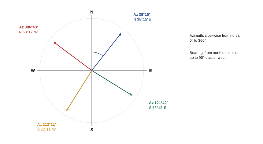
- An azimuth is measured clockwise from north, from 0° to 360°. A line running due east has an azimuth of 90°; due south, 180°; due west, 270°. Azimuths are what total stations and coordinate calculations use.
- A bearing is measured from north or south toward east or west, from 0° to 90°, and is written with the quadrant: N 38°15′ E, S 32°10′ W. Bearings are traditional on legal plans and property descriptions.
| Quadrant | Azimuth range | Bearing from azimuth | Example |
|---|---|---|---|
| NE | 0° to 90° | N (Az) E | Az 38°15′ = N 38°15′ E |
| SE | 90° to 180° | S (180° − Az) E | Az 121°42′ = S 58°18′ E |
| SW | 180° to 270° | S (Az − 180°) W | Az 212°11′ = S 32°11′ W |
| NW | 270° to 360° | N (360° − Az) W | Az 306°43′ = N 53°17′ W |
The back azimuth of a line, the direction looking back from its end to its start, differs by 180°. If line AB has an azimuth of 38°15′, line BA has an azimuth of 218°15′. Carrying azimuths around a traverse uses this rule repeatedly: the azimuth of the next line equals the back azimuth of the previous line plus the angle turned clockwise at the station, minus 360° if the result exceeds 360°.
The total station
A total station measures horizontal angles, vertical angles and slope distances, and its onboard software converts them into horizontal distances, height differences and coordinates. Several kinds are common on construction sites.
- Manual total stations are pointed by the operator, with a second person holding the prism pole.
- Robotic total stations track the prism automatically and are controlled from a data collector at the pole, so one person can lay out points. They are now the standard for building layout.
- Scanning total stations add a laser scanner for capturing as-built surfaces.
Setting up a total station follows a fixed sequence. The tripod is set over the station with the head roughly level. The instrument is centered over the point using the optical or laser plummet and leveled with the foot screws and electronic bubble. The height of instrument above the mark is measured. The operator then orients the instrument by sighting a backsight on a known control point, entering both coordinates so the instrument knows which way is north, and checks the orientation by measuring to a third control point. A check shot that does not agree within a few millimeters means something is wrong: the wrong point, a disturbed control mark, a bumped tripod or a coordinate entry error.
When it is not convenient to set up over a known point, the operator can use a resection, or free station. The instrument is set up anywhere with good visibility and measures angles and distances to two or more control points, usually three or more for a check. The software computes the instrument's position and orientation from those measurements. Resection is standard practice on building sites, where control points are on columns, walls or targets around the perimeter, and the instrument is set up wherever there is a clear view of the work.
Instrument errors and measuring in two faces
Total stations have small mechanical errors that make the line of sight not quite perpendicular to the horizontal axis (collimation error), or the horizontal axis not quite perpendicular to the vertical axis (trunnion axis error), or the vertical circle index not quite correct. Most of these errors are canceled by measuring each angle twice: once in face left, then again after rotating the telescope through 180° in both axes, in face right. The average of the two faces is free of most instrument errors.
Control surveys use multiple sets of two-face observations. Layout is normally done in one face, so the instrument must be checked and calibrated regularly, and important points should be checked from a second setup.
A total station also depends on the tripod and the setup. Sun on one leg, soft ground, frost heave or a worker bumping a leg can rotate or tilt the instrument during the day. Robotic stations can monitor their own tilt and orientation, but the operator should still re-check the backsight frequently and always before setting critical points.
Traverses
A traverse is a series of connected lines whose lengths and angles are measured, used to establish the positions of control points. A closed traverse starts and ends on known points, either returning to its starting point as a loop or ending on a different known point, so its accuracy can be checked. An open traverse does not close and cannot be checked, which is why it should never be used for control.
Construction projects use traverses to set up the site control network: a ring of stable points around the building or along a road that will be used for all later layout. GNSS has replaced traversing for much primary control on open sites, but traverses remain essential in dense urban areas, under tree cover, inside buildings and tunnels, and wherever high precision is needed.
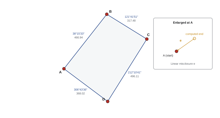
Step 1: angular closure
For a closed loop traverse with n sides, the interior angles must add up to (n − 2) × 180°. The difference between the measured sum and this value is the angular misclosure. If it is within the allowable value, it is distributed equally among the angles, because each angle was measured with similar care. Specifications express the allowable angular misclosure as a constant times the square root of the number of angles, for example 10 seconds × √n for construction control.
Worked problem
Balancing angles
A four-sided loop traverse has measured interior angles of 88°27′38″, 96°33′40″, 89°31′22″ and 85°27′40″. The allowable angular misclosure is 15″ × √n. Balance the angles.
Show solution
- Required sum = (4 − 2) × 180° = 360°00′00″.
- Measured sum = 360°00′20″, so the misclosure is +20″.
- Allowable = 15″ × √4 = 30″. The traverse passes.
- Correction = −20″ ÷ 4 = −5″ per angle: 88°27′33″, 96°33′35″, 89°31′17″ and 85°27′35″, which add to exactly 360°.
Answer: Subtract 5″ from each angle; the balanced angles sum to 360°.
Step 2: azimuths, latitudes and departures
With balanced angles and a known starting azimuth, the azimuth of each line is computed in turn. Each line is then resolved into its north-south component, the latitude, and its east-west component, the departure. North and east are positive; south and west are negative.
If the traverse were perfect, the latitudes would sum to zero and the departures would sum to zero, because the traverse returns to its start. In practice they do not quite, and the resulting gap is the linear misclosure. Dividing the total length of the traverse by the linear misclosure gives the relative precision.
| Line | Azimuth | Distance (ft) | Latitude | Departure |
|---|---|---|---|---|
| A-B | 38°15′33″ | 466.94 | +366.65 | +289.14 |
| B-C | 121°41′51″ | 317.48 | −166.81 | +270.12 |
| C-D | 212°10′41″ | 496.11 | −419.91 | −264.20 |
| D-A | 306°43′36″ | 368.02 | +220.08 | −294.97 |
| Sum | 1,648.55 | +0.01 | +0.09 |
Worked problem
Linear misclosure and precision
Using the table, find the linear misclosure and relative precision of the traverse. The specification requires 1:10,000.
Show solution
- ΣLat = +0.01 ft and ΣDep = +0.09 ft.
- e = √(0.01² + 0.09²) = √0.0082 = 0.091 ft.
- Precision = 1,648.55 ÷ 0.091 ≈ 18,100, so about 1:18,000.
- This exceeds 1:10,000, so the traverse is acceptable.
Answer: e ≈ 0.091 ft; precision about 1:18,000, which passes.
| Typical use | Relative precision often specified |
|---|---|
| Rough site work, topographic detail | 1:3,000 to 1:5,000 |
| Construction layout control, property surveys in many jurisdictions | 1:10,000 |
| Urban property and building control | 1:15,000 to 1:20,000 |
| Primary control for large projects | 1:50,000 or better |
Step 3: adjusting the traverse and computing coordinates
A traverse that passes is adjusted so that it closes exactly. The common method on construction surveys is the compass rule, also called the Bowditch rule. It assumes that errors are proportional to the length of each line, so each latitude and departure is corrected in proportion to the length of its line divided by the total length. Survey software also offers least squares adjustment, which weights each measurement by its expected precision and is the standard for control networks, but the compass rule is easy to do by hand and illustrates the idea.
Worked problem
Compass rule correction and coordinates
Point A has coordinates N 5000.00, E 5000.00. Apply the compass rule to line A-B and compute the coordinates of B.
Show solution
- Latitude correction = −(+0.01) × 466.94 ÷ 1,648.55 = −0.003 ft.
- Departure correction = −(+0.09) × 466.94 ÷ 1,648.55 = −0.025 ft.
- Adjusted latitude = 366.65 − 0.003 = 366.647; adjusted departure = 289.14 − 0.025 = 289.115.
- B: N = 5000.00 + 366.65 = 5366.65; E = 5000.00 + 289.12 = 5289.12 (rounded to 0.01 ft).
Answer: B is at about N 5366.65, E 5289.12.
Once all coordinates are adjusted, the control points are published in a control sheet showing each point's number, description, northing, easting, elevation and how it is marked, often with a sketch or photograph. Every layout crew on the project then works from the same control sheet.
Area from coordinates
Coordinates also make it easy to calculate areas, for example of a lot, a paved area or a stockpile footprint. The coordinate method, sometimes called the shoelace formula, multiplies each northing by the difference of its neighbors' eastings, or equivalently cross-multiplies around the polygon.
Survey software and CAD do this automatically, but the formula is worth knowing because it shows that areas computed from coordinates are only as good as the coordinates themselves.
Practical control on a building site
On a typical building project, the surveyor establishes four or more primary control points around the site, far enough from the excavation that they will not be disturbed, with clear sight lines to the building. Additional control may be set on adjacent buildings or on monuments. As the structure rises, control is transferred to each floor by plumbing up through openings in the slab or by resection from external targets. The construction manager's responsibilities include protecting control points with barriers and paint, keeping equipment and stockpiles away from them, reporting any disturbance, and making sure that control is re-checked against each other at regular intervals.
A disturbed control point is dangerous because everything set from it is wrong in the same way, and the error may not be noticed until a precast panel does not fit or a steel beam is short. If a control point might have been hit, stop using it until the surveyor has checked it from at least two other points.
Common mistakes
MistakeUsing an open traverse for control.
InsteadAlways close a traverse on a known point so it can be checked; an open traverse hides blunders.
MistakeSkipping the check shot after orienting the instrument.
InsteadMeasure to a third control point after every setup and before staking; a bad backsight rotates every point.
MistakeMixing bearings and azimuths.
InsteadConvert every direction to azimuths before calculating latitudes and departures.
MistakeAdding 180° in the wrong place when carrying azimuths.
InsteadNext azimuth = previous azimuth + 180° + clockwise angle, minus 360° if needed; sketch the traverse to check.
MistakeLeaving control points unprotected.
InsteadProtect, flag and fence control; check it regularly and stop using any point that may have moved.
MistakeSetting critical points in one face without checks.
InsteadCheck instrument calibration and confirm critical points from a second setup.
Summary and key terms
- Horizontal angles are measured clockwise from a backsight; total stations report zenith angles for vertical.
- Azimuths run clockwise from north through 360°; bearings run from north or south to 90° east or west.
- A total station must be centered, leveled, oriented on a backsight and checked on a third point.
- Resection lets a total station be set up anywhere by measuring to known control.
- A closed traverse is checked by angular closure, then by the sums of latitudes and departures.
- Relative precision is the traverse length divided by the linear misclosure.
- The compass rule distributes misclosure in proportion to line length; least squares is used for control networks.
- Azimuth
- A direction measured clockwise from north, 0° to 360°.
- Bearing
- A direction measured from north or south toward east or west, 0° to 90°.
- Back azimuth
- The reverse direction of a line, differing by 180°.
- Total station
- An instrument combining angle measurement, EDM and a computer.
- Resection
- Determining an instrument's position by measuring to known control points.
- Face left and face right
- The two telescope positions used to cancel instrument errors.
- Traverse
- A connected series of measured lines used to establish control.
- Latitude
- The north-south component of a line.
- Departure
- The east-west component of a line.
- Linear misclosure
- The distance by which a computed traverse fails to close.
- Compass rule
- An adjustment that distributes misclosure in proportion to line length.
Practice problems
Work each problem on paper first, then reveal the answer to check.
Convert an azimuth of 245°30′ to a bearing.
Show answer
S 65°30′ W.
Convert the bearing N 20°15′ W to an azimuth.
Show answer
339°45′.
Line AB has an azimuth of 72°10′. The clockwise angle at B from A to C is 105°20′. What is the azimuth of BC?
Show answer
72°10′ + 180° + 105°20′ = 357°30′.
A six-sided loop traverse should have interior angles summing to what?
Show answer
(6 − 2) × 180° = 720°.
A line has an azimuth of 120° and length 150.00 ft. Find its latitude and departure.
Show answer
Lat = 150 × cos 120° = −75.00 ft; Dep = 150 × sin 120° = +129.90 ft.
A traverse 2,700 ft long misses closing by 0.20 ft. What is its precision?
Show answer
2,700 ÷ 0.20 = 1:13,500.
Why measure angles in both faces?
Show answer
Averaging face left and face right cancels most instrument errors such as collimation and trunnion axis errors.
What should happen if a check shot to a third control point disagrees by 25 mm?
Show answer
Stop and find the cause (wrong point, disturbed control, entry error or bumped instrument) before setting any points.
Lesson quiz · 5 questions
Score 60% or more to complete this lesson.
Create a free account to save your progress, take quizzes and earn a certificate.