
CON-120 · Lesson 9 of 12 · 26 min
Electrical, lighting and low-voltage drawings
Electrical drawings show how power comes into the building, how it is distributed to panels, equipment, receptacles and lights, and how life safety and communication systems are wired. They are dense with symbols, circuit numbers and schedules, and like mechanical drawings they are partly diagrammatic: they show what is connected to what and roughly where devices go, while the electrician determines exact conduit routes. This lesson explains how to read the electrical legend, the single-line diagram, power plans, panel schedules, lighting plans and fixture schedules, lighting controls, fire alarm drawings and the low-voltage systems for data, security and audio-visual. It also shows how electrical drawings connect to every other discipline. Electrical work must be done by qualified, licensed persons; this lesson is about reading the drawings, not doing the work.
The electrical legend and general notes
Electrical drawings usually start with a long legend of symbols: receptacles of many kinds (duplex, ground fault, dedicated, floor-mounted), switches (single-pole, three-way, dimmer, occupancy sensor), light fixtures, junction boxes, disconnect switches, motors, panels, transformers, fire alarm devices, data outlets, security devices and more. General notes cover the governing code, wiring methods, minimum wire and conduit sizes, mounting heights of devices, grounding and bonding, labeling, testing and coordination with other trades. Mounting heights may also appear on architectural interior elevations, and where they differ, the conflict must be resolved.
In the United States, electrical installations are governed by the National Electrical Code (NFPA 70), adopted by states and municipalities, sometimes with amendments, with inspection by the local authority having jurisdiction. The NEC is revised every three years, the 2026 edition being the most recent, and jurisdictions adopt editions on their own schedules, so the edition in force varies from place to place.
The single-line diagram
The single-line (or one-line) diagram is the map of the electrical distribution system. It shows, using single lines for multi-wire circuits, the path of power from the utility through the building:
- The utility service and metering, often with the utility transformer on a pad outside or in a vault.
- The main service entrance switchboard or switchgear, with its main breaker or switch and its rating in amperes.
- Feeders to distribution panels, motor control centers, transformers and large equipment, labeled with breaker sizes and conductor and conduit sizes.
- Step-down transformers that convert distribution voltage to lower voltage for receptacles and small loads.
- Branch circuit panelboards serving lighting, receptacles and small equipment.
- Emergency and standby power: generators, automatic transfer switches (ATS) and the emergency panels they serve, and uninterruptible power supplies (UPS) for critical loads.
- Grounding and bonding, surge protection and metering.
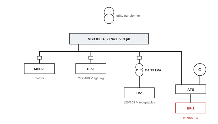
Larger US commercial buildings commonly receive 277/480 V three-phase power, using 277 V for lighting and 480 V for motors and large equipment, with transformers stepping down to 120/208 V for receptacles and small loads. Smaller buildings and houses typically receive 120/208 V three-phase or 120/240 V single-phase service.
The single-line diagram is where to start when you want to understand the electrical system, plan shutdowns and tie-ins in an existing building, or check that a piece of equipment is fed from the right panel. Long-lead items such as switchgear, transformers and generators are identified here, and they often control the electrical schedule.
Power plans
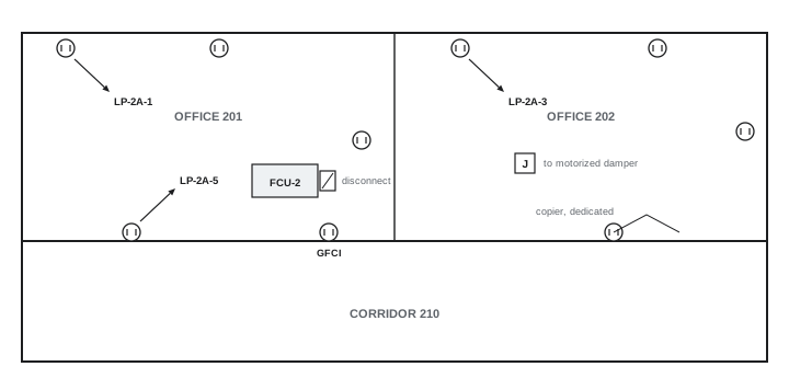
Power plans show receptacles, equipment connections, junction boxes, disconnects, floor boxes and other power devices on each floor, with the circuit that feeds each device. Circuits are usually shown in one of two ways:
- Home runs: an arrow at the end of a short line from a device, labeled with the panel and circuit numbers, such as "LP-2A-12,14", meaning circuits 12 and 14 in panel LP-2A. The electrician routes the actual conduit and wire from the device to the panel.
- Circuited lines: lines (curved or straight) connecting devices on the same circuit, with tick marks sometimes showing the number of conductors.
Equipment connections are shown by symbols at the equipment with notes giving voltage, phase, amperes or kilowatts and the disconnect requirements, and they refer to the mechanical equipment schedules. Floor boxes and poke-throughs in slabs, power to furniture systems and counters, and receptacles at specific heights in labs and kitchens require careful coordination with the architectural and furniture layouts.
Panel schedules
Each panelboard has a panel schedule, a table showing every circuit with its number, description, breaker size and number of poles, and connected load, usually in volt-amperes (VA) per phase. The schedule header gives the panel name, voltage and phase, main breaker or main lugs, bus rating, mounting, location and fed-from information. Totals at the bottom show the connected load per phase and the total load, sometimes with demand factors.
| Ckt | Description | Breaker | Load A (VA) | Load B (VA) | Load C (VA) |
|---|---|---|---|---|---|
| 1 | Receptacles, offices 201–202 | 20 A, 1P | 1,080 | ||
| 3 | Receptacles, corridor 210 | 20 A, 1P | 720 | ||
| 5 | Copier, room 205 | 20 A, 1P | 1,500 | ||
| 7 | Fan coil FCU-2 | 15 A, 1P | 600 | ||
| 9 | Receptacles, washroom (GFCI) | 20 A, 1P | 360 | ||
| 11 | Hand dryers, washroom | 20 A, 1P | 1,800 | ||
| Totals | 1,680 | 1,080 | 3,300 |
Worked problem
Checking a panel schedule
Using the panel schedule excerpt above: (a) What is the total connected load shown? (b) Which phase is most heavily loaded, and by how much more than the lightest? (c) Circuit 11 serves hand dryers at 1,800 VA on a 20 A, 120 V circuit. Electrical codes generally limit continuous loads to 80 % of the breaker rating. Is circuit 11 within that limit if the load is continuous?
Show solution
- Total connected load: 1,680 + 1,080 + 3,300 = 6,060 VA.
- Phase C carries 3,300 VA and phase B 1,080 VA, a difference of 2,220 VA. Phase C carries more than half of the load shown, so the circuits are poorly balanced.
- A 20 A, 120 V circuit has a capacity of 20 × 120 = 2,400 VA. At 80 %, the continuous limit is 1,920 VA.
- The 1,800 VA load is below 1,920 VA, so it is within the 80 % limit, though with little spare capacity.
Answer: The panel shows 6,060 VA, with phase C much more heavily loaded than B; the designer or electrician may rebalance by moving circuits. Circuit 11 at 1,800 VA is within the 80 % continuous limit of 1,920 VA. Final judgments on loads and code compliance belong to the electrical engineer and inspector.
Panel schedules are useful for checking that every piece of equipment has a circuit, that breaker sizes match equipment nameplates, that spare circuits and space exist for future loads, and that the panel is properly fed on the single-line diagram.
Lighting plans and fixture schedules
Lighting plans show light fixtures, usually drawn to scale in their actual positions and coordinated with the reflected ceiling plan, each tagged with a fixture type letter or code. A lighting fixture schedule (luminaire schedule) lists each type with its description, mounting (recessed, surface, pendant, wall), dimensions, lamp or LED source, lumens, color temperature, wattage, voltage, driver and dimming type, and the basis-of-design manufacturer and catalog number. Notes on the plans show switching or control zones, often with lower-case letters beside fixtures that match letters beside switches or control devices.
Emergency lighting and exit signs are shown with distinct symbols or shading. Emergency fixtures may be normal fixtures powered from an emergency circuit, fixtures with integral battery packs, or separate emergency lighting units, and they must provide the illumination required along exit routes when normal power fails.
Worked problem
Lighting power from the schedule
An open office of 40 ft × 30 ft has 16 type A fixtures. The fixture schedule gives type A as 2 × 2 recessed LED, 3,400 lumens, 30 W. (a) What is the total connected lighting power and the lighting power density in W/ft²? (b) The energy code allowance used by the designer for open offices is about 0.65 W/ft². Is the design within it?
Show solution
- Total power: 16 × 30 W = 480 W.
- Area: 40 × 30 = 1,200 ft².
- Lighting power density = 480 ÷ 1,200 = 0.40 W/ft².
- This is well below the 0.65 W/ft² allowance used for the comparison.
Answer: The office uses 480 W, 0.40 W/ft², within the allowance. Actual allowances depend on the energy code and compliance path (for example, ASHRAE 90.1 or the IECC), which the designer documents (CON-140).
Lighting controls
Modern energy codes require automatic lighting controls: occupancy or vacancy sensors that turn lights off when spaces are empty, daylight sensors that dim fixtures near windows, time schedules, and in many spaces, multilevel or dimming controls. Control systems may be simple standalone devices or networked lighting control systems with wireless sensors and software. Drawings show control devices, zones and wiring diagrams, and specifications describe sequences and programming. Lighting controls are a frequent source of commissioning problems, so careful reading of the control intent pays off.
Fire alarm drawings
Fire alarm drawings show the fire alarm control panel and annunciator, initiating devices (smoke and heat detectors, manual pull stations, sprinkler flow and tamper switches, duct detectors), notification appliances (horns, strobes, speakers), and connections to other systems such as door hold-open releases, elevator recall, fan shutdown, smoke control and fire dampers. Riser diagrams show the system architecture. Like sprinkler systems, fire alarm systems are often finalized in shop drawings by the fire alarm contractor, with device locations, circuits and battery calculations, and they must be verified before occupancy.
In the United States, fire alarm systems are designed, installed, tested and maintained to NFPA 72, the National Fire Alarm and Signaling Code, as referenced by the IBC and IFC and adopted locally. Acceptance testing witnessed by the authority having jurisdiction is normally required before occupancy.
Low-voltage and communications systems
Many projects have a separate set of telecommunications or technology drawings (often with the designator T) for low-voltage systems:
- Structured cabling: data and voice outlets, cable trays, telecommunications rooms with racks, backbone cabling between floors, and service entrance for carriers.
- Security: access control card readers, electrified door hardware, intrusion detection and video surveillance cameras.
- Audio-visual: displays, projectors, speakers and control systems in meeting rooms and classrooms.
- Other systems: nurse call, intercom, distributed antenna systems for radio and cellular coverage, and building automation networks.
Low-voltage drawings must be coordinated with power (for outlets and equipment), architectural (for room layouts and ceiling access) and door hardware (for card readers and electrified locks). These systems are often installed late and changed often, so coordination drawings and clear responsibility matrices help avoid gaps.
Coordinating electrical drawings with other disciplines
Electrical drawings connect to almost everything. Typical checks include:
- Mechanical: every motor, pump, fan, VAV box and unit heater in the mechanical schedules has a circuit, disconnect and matching voltage.
- Plumbing: water heaters, pumps, electronic faucets and flush valves have power.
- Architectural: receptacles and switches suit furniture, millwork and door swings; light fixtures fit the ceiling grid; devices meet accessibility heights.
- Structural: conduits in slabs do not conflict with reinforcing or tendons; electrical rooms and equipment pads are shown.
- Door hardware and security: electrified hardware, card readers and automatic operators are powered and connected.
- Civil: site lighting, utility duct banks and transformer pads are coordinated with grading and underground pipes.
Common mistakes
MistakeReading power plans without the single-line diagram.
InsteadStart with the single-line diagram to understand the system.
MistakeAssuming every mechanical item has a circuit.
InsteadCheck the panel schedules against the mechanical equipment schedules.
MistakeIgnoring switching letters on lighting plans.
InsteadMatch fixture letters to control devices and zones.
MistakeTreating low-voltage systems as an afterthought.
InsteadCoordinate data, security and AV early with power and doors.
MistakeDoing electrical work without qualifications.
InsteadLeave electrical installation to licensed electricians under permit.
Summary and key terms
- The electrical legend and general notes define symbols, codes and wiring requirements.
- The single-line diagram maps power from the utility to panels and emergency systems.
- Power plans show devices with home runs labeled by panel and circuit.
- Panel schedules list circuits, breakers and loads per phase.
- Lighting plans and fixture schedules define fixture types, controls and emergency lighting.
- Fire alarm and low-voltage systems are often finalized in contractor shop drawings.
- Electrical drawings must be coordinated with every other discipline.
- Single-line diagram
- Diagram of the power distribution system using single lines.
- Panelboard
- Enclosure of breakers distributing branch circuits.
- Home run
- Arrow showing a circuit returning to its panel.
- Panel schedule
- Table of circuits, breakers and loads in a panel.
- Feeder
- Circuit supplying a panel or large equipment.
- Automatic transfer switch
- Switch moving loads to the generator when utility power fails.
- Luminaire schedule
- Table of light fixture types and data.
- Lighting power density
- Lighting power per unit floor area.
- Initiating device
- Fire alarm device that detects or reports a fire.
- Structured cabling
- Standardized data and voice cabling system.
Practice problems
Work each problem on paper first, then reveal the answer to check.
Where would you look to see which panel feeds a distribution transformer?
Show answer
The single-line diagram.
What does "LP-3B-7,9" beside a home run mean?
Show answer
Circuits 7 and 9 in panel LP-3B.
Capacity of a 15 A, 120 V circuit?
Show answer
1,800 VA.
80 % continuous limit of a 20 A, 120 V circuit?
Show answer
1,920 VA.
Loads of 2,100, 1,900 and 2,000 VA per phase total?
Show answer
6,000 VA.
What do lower-case letters beside fixtures usually indicate?
Show answer
Switching or control zones.
20 fixtures at 25 W in 100 m². Lighting power density?
Show answer
5 W/m².
Name two fire alarm initiating devices.
Show answer
Smoke detectors, heat detectors, pull stations, flow switches.
Name three low-voltage systems.
Show answer
Data, security, AV, nurse call, DAS.
Why compare mechanical schedules with panel schedules?
Show answer
To confirm every piece of equipment has power with matching characteristics.
Lesson quiz · 5 questions
Score 60% or more to complete this lesson.
Create a free account to save your progress, take quizzes and earn a certificate.