
CON-120 · Lesson 7 of 12 · 25 min
Structural drawings: foundations, framing, reinforcing and steel
Structural drawings show the skeleton of the building: the foundations that carry it to the ground, the columns and walls that hold it up, the beams, joists and slabs that span between them, and the bracing and shear walls that resist wind and earthquakes. They are prepared and sealed by the structural engineer, and they are among the most precise drawings in the set, because structural errors are expensive to fix and can be dangerous. Structural drawings have their own conventions for notes, schedules, member designations and reinforcing callouts. This lesson explains how to read structural general notes, foundation plans and schedules, framing plans for concrete, steel and wood, reinforcing callouts and bar lists, steel member designations and connection details. It focuses on reading; CON-110 and CON-111 cover the materials and methods, and CON-240 explains structural behavior.
Structural general notes
The first structural sheet usually contains the general notes, which are dense, important and often overlooked. They typically include:
- The governing building code and the design standards for each material.
- Design loads: dead loads, live loads for each type of floor, roof snow loads, wind and seismic design parameters, and special loads such as equipment or vehicles.
- Foundation design data: the geotechnical report reference, allowable or factored bearing pressures, pile capacities and requirements for inspection of bearing surfaces.
- Material specifications: concrete strengths and exposure classes for each element, reinforcing steel grade, structural steel grades, bolt and weld requirements, wood species and grades, and masonry strengths.
- Cover to reinforcement, lap splice requirements, typical reinforcing at openings and corners, and other typical requirements.
- Requirements for shop drawings, delegated design (items such as precast, stairs, steel connections or open-web joists designed by the supplier's engineer), inspections and testing.
- Temporary bracing and construction sequence responsibilities, which usually rest with the contractor.
US structural general notes typically cite the International Building Code as adopted locally, with ASCE 7 for loads, ACI 318 for structural concrete, ASTM A615 or A706 for reinforcing steel, AISC 360 for steel buildings (with ASTM A992 for wide-flange shapes and A500 for HSS), the AWC National Design Specification (NDS) for wood and TMS 402/602 for masonry. Snow, wind and seismic parameters come from ASCE 7 and its hazard data for the site.
Read the general notes before the plans. They tell you, for example, that "all footings shall bear on undisturbed native soil or engineered fill with a minimum allowable bearing pressure of 150 kPa (3,000 psf), verified by the geotechnical engineer", or that "contractor is responsible for the design of all temporary shoring and bracing", requirements that affect cost and schedule but may appear nowhere else.
Foundation plans
The foundation plan shows the foundation elements in plan, located by grid lines:
- Spread footings, tagged with marks such as F1, F2, F3 that refer to a footing schedule giving size, thickness and reinforcing.
- Strip footings under walls, with their widths and reinforcing, often shown in sections.
- Pile caps and piles, with pile types, capacities and cut-off elevations.
- Foundation walls, grade beams, pilasters and piers.
- Top of footing or top of pile cap elevations, often noted as T/F EL or T/O FTG.
- Slab-on-grade thickness, reinforcing, joints and depressions, and under-slab drainage or vapor retarder notes.
- Steps in footings, sumps, pits (elevator, sump), trenches and openings.
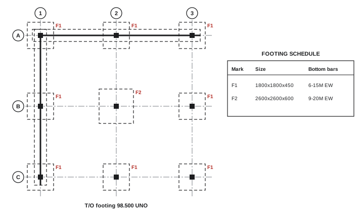
| Mark | Size (L × W × D) | Bottom reinforcing | Top reinforcing | Remarks |
|---|---|---|---|---|
| F1 | 6'-0" × 6'-0" × 1'-6" | 6-#5 E.W. | — | Exterior columns |
| F2 | 8'-6" × 8'-6" × 2'-0" | 9-#6 E.W. | — | Interior columns |
| F3 | 10'-6" × 6'-0" × 2'-0" | 10-#6 long, 8-#5 short | 6-#5 long | Combined footing at stair |
Reinforcing callouts
Reinforcing steel (rebar) is described by callouts that give the number of bars, their size, their spacing or location, and their position. Typical forms are:
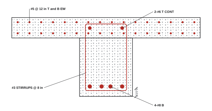
In the United States, bar sizes are designated by number, the nominal diameter in eighths of an inch: #3 (3/8 in) through #11, plus #14 and #18 (ASTM A615/A706). A callout such as "#5 @ 12" O.C. T&B E.W." means #5 bars spaced at 12 in on center, top and bottom layers, each way. "6-#5 E.W." means six #5 bars in each direction. "4-#8 CONT. T" means four continuous #8 bars at the top of a beam. Stirrups and ties are called out as, for example, "#3 STIRRUPS @ 8"". Grade 60 (60,000 psi yield) is the common grade.
Common abbreviations in reinforcing callouts include T (top), B or BOT (bottom), E.W. (each way), E.F. (each face), CONT. (continuous), ALT. (alternate), DWL (dowel), STIRR (stirrups), HK (hook) and L.S. or LAP (lap splice). Positions are shown in sections, with bars cut in section drawn as dots and bars running along the section as lines.
Worked problem
Counting and weighing bars from a callout
A slab panel measures 24'-0" by 20'-0". The callout is "#5 @ 12" B E.W." with 1 1/2" cover at the edges. #5 bars weigh 1.043 lb/ft. (a) How many bars run in each direction? (b) What is the total weight of bottom reinforcing for the panel, ignoring laps?
Show solution
- Bars running in the 24 ft direction are spaced across the 20 ft width. Usable width = 20 ft − 2 × 1.5 in = 19.75 ft. Number = 19.75 ÷ 1 + 1 = 20.75, rounded up to 21 bars.
- Each of these bars is 24 ft − 3 in = 23.75 ft long, so they total 21 × 23.75 = 498.8 ft.
- Bars running in the 20 ft direction are spaced across the 24 ft length. Usable length = 23.75 ft. Number = 23.75 + 1 = 24.75, rounded up to 25 bars, each 19.75 ft long: 25 × 19.75 = 493.8 ft.
- Total length ≈ 498.8 + 493.8 = 992.6 ft. Weight = 992.6 × 1.043 ≈ 1,035 lb.
Answer: About 21 bars one way and 25 the other, totaling roughly 1,035 lb before laps and waste. Detailers and estimators apply their own rules for counting, laps and hooks (CON-200).
Structural drawings show the design reinforcing; the reinforcing supplier's detailer then produces placing drawings (shop drawings) and bar lists showing every bar with a mark, quantity, size, length and bending shape. Ironworkers place the steel from the placing drawings, and inspectors check it against both the placing drawings and the structural drawings before concrete is placed.
Concrete framing plans and schedules
For concrete buildings, framing plans show slabs, beams, drop panels, column capitals and openings for each floor, with slab thickness, top of slab elevations, beam marks and reinforcing or references to schedules and sections. Column schedules list each column mark with its size and vertical reinforcing and ties for each story, often in a grid-like table with levels down the side. Beam schedules give beam sizes and top, bottom and stirrup reinforcing. Post-tensioned slabs have tendon layout plans showing tendon profiles and anchor locations, which must never be drilled or cored without scanning and approval.
Openings, sleeves and embedded items in slabs and walls are critical coordination items. Structural drawings show major openings and typical reinforcing around openings, but sleeves for mechanical and electrical services are often coordinated during construction. Coring or cutting concrete after placement can cut reinforcing or tendons, so the structural engineer's approval is needed.
Steel framing plans
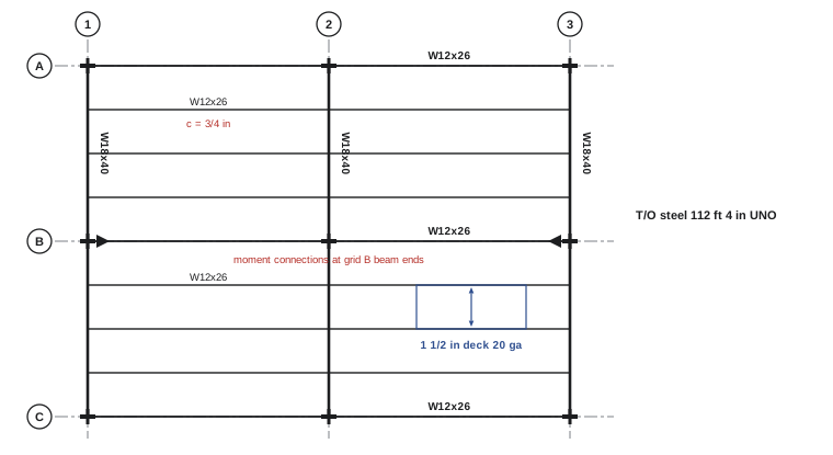
Steel framing plans show beams, girders, joists and bracing for each floor and the roof. Each member is drawn as a single line between supports, labeled with its size, and the columns appear at grid intersections. Conventions include:
- Member labels along the line, such as W310×39 or W12×26, with camber if required (for example, "C = 20" or "c = 3/4"").
- Top of steel elevations, given as a note for the whole floor with exceptions noted.
- Symbols showing connections: a simple line end for shear (pinned) connections, a small solid triangle or flag for moment connections, and notes for special connections.
- Open-web steel joists (OWSJ) or steel joists shown as lines with spacing and designations, often designed by the joist supplier.
- Steel deck direction, shown by a symbol with arrows or a hatch indicating the span direction, with deck type and gauge noted.
- Bracing, drawn as diagonal lines in plan or on bracing elevations, with member sizes.
- Openings and reinforcing frames for roof drains, shafts and equipment.
Steel member designations
Steel shapes are named by their cross-section type and size. The most common are:
| Shape | Canadian (metric) example | US (imperial) example | Meaning |
|---|---|---|---|
| Wide-flange (W) | W310×39 | W12×26 | Nominal depth (mm or in) × mass (kg/m) or weight (lb/ft) |
| Hollow structural section (HSS) | HSS152×152×9.5 | HSS6×6×3/8 | Outside dimensions × wall thickness |
| Round HSS or pipe | HSS168×6.4 | HSS6.625×0.250 | Outside diameter × wall thickness |
| Angle (L) | L102×102×9.5 | L4×4×3/8 | Leg lengths × thickness |
| Channel (C) | C250×30 | C10×20 | Depth × mass or weight per length |
| Plate (PL) | PL12×200 | PL1/2×8 | Thickness × width |
Because W-shape designations give mass or weight per unit length, steel tonnage is easy to estimate from framing plans: multiply each member's length by its unit mass and add them up. A 9 m W310×39 weighs about 9 × 39 = 351 kg; a 30 ft W12×26 weighs about 30 × 26 = 780 lb. Fabricators add connection material, typically a modest percentage.
Connections are shown in typical connection details and specific details. Many projects delegate connection design to the fabricator's engineer, with the structural drawings giving the design forces or reactions. Welds are shown with standard weld symbols: an arrow pointing to the joint, a reference line, and symbols for the weld type (such as a triangle for a fillet weld), size, length and whether it is welded in the shop or the field (a flag) and all round (a circle). Bolts are specified by diameter, grade (such as ASTM F3125 Grade A325 or A490) and tightening type: snug-tight, pretensioned or slip-critical.
Wood framing drawings
Wood-framed buildings, including houses, apartments and an increasing number of mid-rise and mass timber buildings, have framing plans showing:
- Joist, rafter and truss sizes, spacing and direction, such as "2×10 @ 400 o.c." (or "2x10 @ 16" o.c."), or engineered I-joists and floor trusses designated by depth and series.
- Beams and headers, often engineered lumber such as laminated veneer lumber (LVL) or glued-laminated timber (glulam), given by size and number of plies, such as "3-1 3/4 × 11 7/8 LVL".
- Bearing walls, point loads and posts that must carry loads down through the floors to the foundation, sometimes highlighted to show the load path.
- Shear walls with their sheathing, nailing schedule and hold-down anchors at their ends, and diaphragm nailing for floors and roofs.
- Trusses, usually designed by the truss manufacturer; the structural drawings show layout and loads, and the manufacturer's truss drawings, sealed by its engineer, show the members and connections.
Mass timber buildings using cross-laminated timber (CLT) panels and glulam columns and beams have drawings that look more like steel or precast drawings, with panel layouts, connection details and fabrication by the supplier from a shared model (CON-111 covers wood and mass timber construction).
Sections and details
Structural sections and details show how members connect and how reinforcing is arranged at critical locations: footing-to-wall junctions, slab edges, beam-column joints, openings, stair and elevator supports, roof edges and connections between different systems, such as steel beams bearing on concrete walls. Typical details, such as "typical reinforcing at slab openings" or "typical steel beam to column shear connection", apply wherever the condition occurs (TYP). Specific details are referenced from plans by callouts.
Structural and architectural sections of the same location should agree on dimensions, levels and the location of structure. A common check is to compare the architectural wall section with the structural detail at each floor: does the slab edge line up with the cladding support, does the beam depth leave room for the ceiling and ducts, and are the top of steel and top of slab elevations consistent?
Common mistakes
MistakeSkipping the structural general notes.
InsteadRead loads, materials, inspections and contractor responsibilities first.
MistakeMisreading E.W., T&B or E.F. in rebar callouts.
InsteadCheck the section and abbreviations for bar positions.
MistakeCoring or cutting slabs without approval.
InsteadScan for rebar and tendons and get the engineer's approval.
MistakeAssuming delegated items are fully designed on the drawings.
InsteadIdentify delegated design and plan for supplier engineering and submittals.
MistakeBuilding from structural drawings without checking architectural levels.
InsteadCompare slab, steel and envelope elevations across disciplines.
Summary and key terms
- Structural general notes give codes, loads, materials, inspections and responsibilities.
- Foundation plans use footing marks linked to schedules and give top of footing elevations.
- Rebar callouts give number, size, spacing and position of bars.
- Placing drawings and bar lists turn design reinforcing into fabrication information.
- Steel framing plans label members by shape and size, with connection and deck symbols.
- W-shape designations give unit mass or weight, making tonnage easy to estimate.
- Wood framing plans show joists, beams, bearing walls, shear walls and trusses.
- Structural general notes
- Notes giving codes, loads, materials and requirements.
- Footing schedule
- Table of footing marks with sizes and reinforcing.
- Rebar callout
- Note giving bar number, size, spacing and position.
- Each way (E.W.)
- Reinforcing in both directions.
- Placing drawing
- Detailer's drawing showing every bar for placement.
- Bar list
- Schedule of bar marks, sizes, lengths and shapes.
- W-shape
- Wide-flange steel section designated by depth and unit mass or weight.
- Moment connection
- Connection transferring bending between members.
- Delegated design
- Design of a component by the supplier's engineer.
- Shear wall
- Wall designed to resist lateral wind and seismic forces.
Practice problems
Work each problem on paper first, then reveal the answer to check.
Where would you find the specified concrete strength for footings?
Show answer
Structural general notes or the specifications.
What does F2 on a foundation plan refer to?
Show answer
A footing mark in the footing schedule.
What does "T&B E.W." mean?
Show answer
Top and bottom layers, each way.
How many bars at 200 mm spacing across a 4 000 mm width with 50 mm cover?
Show answer
3 900 ÷ 200 + 1 = 20.5, so 21 bars.
What is the mass of a 7.5 m W250×33?
Show answer
About 248 kg.
What does the 26 in W12×26 represent?
Show answer
Weight in pounds per foot.
What does a flag on a weld symbol indicate?
Show answer
A field weld.
Who usually designs open-web steel joists or wood trusses?
Show answer
The supplier's engineer (delegated design).
What must be done before coring a post-tensioned slab?
Show answer
Scan for tendons and get the engineer's approval.
Name one cross-discipline check between structural and architectural sections.
Show answer
Slab edges versus cladding, beam depth versus ceilings, consistent elevations.
Lesson quiz · 5 questions
Score 60% or more to complete this lesson.
Create a free account to save your progress, take quizzes and earn a certificate.