
CON-110 · Lesson 9 of 12 · 24 min
Reinforcing steel: grades, sizes, detailing and placing
Concrete is strong in compression but weak in tension, with a tensile strength only about a tenth of its compressive strength. When a concrete beam bends, the bottom is stretched and would crack and fail suddenly without reinforcement. Steel reinforcing bars (rebar), placed where tension develops, carry those tensile forces, and the combination, reinforced concrete, is the basis of most modern foundations, slabs, walls and frames. Reinforcement also controls shrinkage and temperature cracking, confines concrete in columns and resists shear. The steel only works if it is the right grade and size, in the right place, with the right cover and properly spliced and anchored, which makes reinforcing one of the most closely inspected parts of concrete construction. This lesson covers reinforcing materials, bar sizes and weights, cover, splices and development, detailing and shop drawings, placing and supports, and inspection before concrete placement.
Why reinforcement works
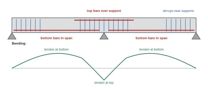
Steel and concrete work together because concrete bonds to the deformed (ribbed) surface of the bars; steel and concrete expand by almost the same amount with temperature changes; and the alkaline environment of concrete protects steel from corrosion as long as the cover is adequate and free from cracks and chlorides. Designers place reinforcement where tension occurs: at the bottom of simply supported beams and slabs, at the top over supports where slabs and beams are continuous, around the perimeter of columns with ties or spirals, and in both faces of walls and footings as required. A bar installed in the wrong layer, such as top bars placed at the bottom, can make an element dangerously weak even if every bar is present.
Reinforcing materials and grades
Most reinforcement is hot-rolled carbon steel deformed bars. Grades are identified by their minimum yield strength.
In the United States, reinforcing bars are specified under ASTM A615 (carbon steel), most commonly Grade 60 (yield strength 60,000 psi, about 420 MPa), and ASTM A706 (low-alloy, weldable and more ductile, required for many seismic applications), with Grades 80 and 100 increasingly used in heavily loaded members. Epoxy-coated bars follow ASTM A775 or A934, galvanized bars ASTM A767, stainless bars ASTM A955 and GFRP bars ASTM D7957. Rolled-in marks identify the mill, size, type of steel and grade.
Corrosion-resistant reinforcement is used in aggressive environments such as parking structures, bridge decks and marine structures: epoxy-coated bars (which must be handled with padded slings and touched up where damaged), galvanized bars, stainless steel bars and non-metallic GFRP bars. Welded wire reinforcement (welded wire fabric or mesh) in sheets or rolls is common in slabs-on-grade, toppings and walls. Steel and synthetic fibers can replace some secondary reinforcement in slabs, and prestressing tendons are used in post-tensioned and precast prestressed concrete, a specialized area covered in later courses.
Bar sizes and weights
Canada uses metric bar designations based on the approximate diameter in millimeters (10M, 15M, 20M and so on), while the United States uses numbers that represent the nominal diameter in eighths of an inch (#4 is 4/8 in, or 1/2 in). The two systems are not interchangeable, although some sizes are close. Weights are used for estimating, ordering and payment.
| Canadian bar | Area (mm²) | Mass (kg/m) | US bar | Area (in²) | Weight (lb/ft) |
|---|---|---|---|---|---|
| 10M | 100 | 0.785 | #3 | 0.11 | 0.376 |
| 15M | 200 | 1.570 | #4 | 0.20 | 0.668 |
| 20M | 300 | 2.355 | #5 | 0.31 | 1.043 |
| 25M | 500 | 3.925 | #6 | 0.44 | 1.502 |
| 30M | 700 | 5.495 | #7 | 0.60 | 2.044 |
| 35M | 1000 | 7.850 | #8 | 0.79 | 2.670 |
| 45M | 1500 | 11.775 | #9 | 1.00 | 3.400 |
| 55M | 2500 | 19.625 | #10 | 1.27 | 4.303 |
Steel weighs about 7,850 kg/m³ (490 lb/ft³), so the mass per meter of a bar is its area in square meters times 7,850; for example, a 15M bar with an area of 200 mm² (0.0002 m²) weighs 0.0002 × 7,850 = 1.57 kg/m.
Concrete cover
Concrete cover is the distance from the surface of the concrete to the nearest surface of reinforcement, including ties and stirrups. Cover protects steel from corrosion and fire and allows the bars to develop bond. Required cover increases with the severity of exposure. Typical values are:
Under ACI 318, concrete cast against and permanently in contact with ground requires 3 in of cover; concrete exposed to weather or in contact with ground requires 2 in for #6 bars and larger and 1-1/2 in for #5 bars and smaller; interior slabs, walls and joists not exposed to weather need 3/4 in for #11 bars and smaller, and interior beams and columns 1-1/2 in to the ties. Project drawings and specifications may require more.
Cover that is too small leads to corrosion, spalling and reduced fire resistance; cover that is too large reduces the effective depth of the member and its strength, and can increase surface cracking. Cover is controlled by supports, spacers and careful placing, and is one of the first things inspectors check.
Development, splices and hooks
A bar can only carry its full force if it is embedded far enough in concrete for bond to transfer that force. The required embedment is the development length, which depends on the bar size, steel grade, concrete strength, cover, spacing, bar position (top bars with deep concrete beneath them develop less bond) and coating (epoxy reduces bond). Where bars cannot extend far enough, standard hooks (90° or 180° bends) or headed bars provide anchorage.
Bars come in limited stock lengths, commonly up to 12 m or 18 m in Canada and 40 ft or 60 ft in the United States, so long runs must be spliced. The main methods are:
- Lap splices: overlapping two bars by a specified length, often in the range of 40 to 60 bar diameters depending on conditions, and tying them together. Laps are the cheapest method but congest reinforcement.
- Mechanical couplers: threaded, swaged or grouted sleeves that join bars end to end, used for large bars and congested areas.
- Welded splices: only with weldable steel (400W or A706) and qualified welders following welding standards (CSA W186 or AWS D1.4).
Splice lengths and locations are shown on the drawings or schedules; laps should be staggered where required and kept out of high-stress zones as the designer directs. Bending of bars must follow minimum bend diameters to avoid cracking the steel, and field bending of embedded bars or heating bars to bend them is prohibited unless the engineer approves.
Detailing, shop drawings and bar lists
Structural drawings show the reinforcement required, but the reinforcing supplier prepares detailed shop drawings (placing drawings) and bar lists that show every bar with a bar mark, size, number, length, bend shape and location. Detailers follow industry standard practice manuals and the standard bend shapes they define.
In the United States, detailers follow the CRSI Manual of Standard Practice and ACI 315 detailing guidance.
Shop drawings are submitted to the engineer for review before fabrication. The fabricator cuts and bends bars in a shop, bundles and tags them by bar mark, and delivers them in sequence. On site, bars are stored off the ground on dunnage, sorted by tag, and protected from mud, oil and excessive rust. Light rust is acceptable and can improve bond, but loose scale, mud, oil and form release agent must be removed.
Worked problem
Estimating rebar for a slab
A slab-on-grade is 8 m by 6 m with a single mat of 15M bars at 300 mm on center each way, with 40 mm end and edge cover. Estimate the number of bars, total length and mass. Add 5 % for laps and waste. (For comparison, a similar slab 26 ft by 20 ft with #5 bars at 12 in each way and 1-1/2 in edge cover is also given.)
Show solution
- Bars running the 8 m direction are spaced across the 6 m width: (6,000 − 80) ÷ 300 = 19.7 spaces, round up to 20 spaces, giving 21 bars.
- Length of each: 8.00 − 0.08 = 7.92 m; total 21 × 7.92 = 166.3 m.
- Bars running the 6 m direction are spaced along the 8 m length: (8,000 − 80) ÷ 300 = 26.4, round up to 27 spaces, giving 28 bars of 5.92 m = 165.8 m.
- Total length: 166.3 + 165.8 = 332.1 m; mass 332.1 × 1.570 ≈ 521 kg; plus 5 % ≈ 547 kg.
- Imperial comparison: (240 − 3) ÷ 12 = 19.75, so 20 spaces and 21 bars of 25.75 ft = 540.8 ft; (312 − 3) ÷ 12 = 25.75, so 26 spaces and 27 bars of 19.75 ft = 533.3 ft; total 1,074 ft × 1.043 lb/ft ≈ 1,120 lb, plus 5 % ≈ 1,180 lb.
Answer: About 49 bars, 332 m and 547 kg of 15M including allowances (about 1,180 lb of #5 for the imperial slab).
Placing reinforcement
Ironworkers (rodmen) place and tie reinforcement according to the placing drawings. Key practices include:
- Supports: bars are held at the correct height by chairs, bolsters, slab bolsters and precast concrete blocks (dobies). Supports on soil or vapor barriers need plates or concrete blocks so they do not sink. Plastic or coated supports are used where rust stains on exposed surfaces are unacceptable.
- Spacing: bar spacing must meet the drawings and allow concrete and aggregate to flow around bars; minimum clear spacing is typically the larger of about 1.4 times the bar diameter, 1.4 times the maximum aggregate size or 30 mm in Canada, and the larger of 1 in, the bar diameter or 4/3 of the maximum aggregate size in the United States.
- Tying: bars are tied with soft steel wire at intersections and splices so the cage does not move during placement; not every intersection needs tying in slabs, but mats must be stable enough to walk on.
- Top mats: top bars in slabs and footings are supported on high chairs or standees so they are not pushed down by workers.
- Dowels and starter bars: dowels into walls and columns are set to correct projection and position, often with templates.
- Openings: extra bars around openings and sleeves as detailed.
- Safety: protruding vertical bars are capped or bent over to prevent impalement; bundles are lifted with proper rigging.
Walking on reinforcement during concrete placement can displace it, so runways or careful practices are used, and an ironworker should stand by during the pour to correct displaced bars.
Inspection before concrete placement
Before concrete is placed, the contractor, the engineer or inspector and often the testing agency inspect reinforcement. A typical checklist includes: correct bar sizes, grades and numbers; spacing and layer positions; cover to forms and ground; lap lengths and locations; hooks and anchorage; dowels and embedded items; supports and ties secure; cleanliness of bars and forms; epoxy coating damage repaired; and conformance with the reviewed shop drawings. Deficiencies are corrected before concrete is ordered. Some jurisdictions require municipal inspection of footing and foundation reinforcement for houses, and larger projects require field reviews by the structural engineer or special inspections.
Coordination with other trades
Reinforcement does not exist in isolation: electrical conduits, plumbing sleeves, post-tensioning tendons, embedded plates and anchor bolts all compete for space within the same concrete. Conflicts are common, especially in thin slabs, beam-column joints and walls with many openings. Electricians may want to run conduits through slabs, but large conduits or clusters of conduits can reduce the strength of the slab and interfere with reinforcement, so specifications limit their size and spacing. Cutting reinforcement to make room for a sleeve or conduit is not permitted without the engineer's approval and usually requires additional trim bars. Coordination drawings and building information models help find conflicts before work reaches the site, and a pre-pour walk-through with all trades confirms that everything is in place and that no bars have been displaced or cut.
Common mistakes
MistakePlacing top bars at the bottom or vice versa.
InsteadCheck layers against the drawings.
MistakeSetting chairs directly on soft soil or vapor barrier.
InsteadUse plates or concrete blocks.
MistakeWelding ordinary non-weldable bars.
InsteadWeld only weldable steel with qualified procedures.
MistakeLeaving vertical bars uncapped.
InsteadCap or bend over protruding bars.
MistakeTreating Canadian and US bar sizes as interchangeable.
InsteadUse the size system in the drawings.
Summary and key terms
- Reinforcement carries tension that concrete cannot.
- Common grades are 400W in Canada and Grade 60 in the United States.
- Metric bars are named 10M, 15M and so on; US bars #3, #4 and so on.
- Cover protects steel from corrosion and fire; 75 mm or 3 in against earth.
- Development length, hooks, laps and couplers anchor and join bars.
- Shop drawings and bar lists define every bar; supports hold bars in place.
- Inspect size, spacing, cover, laps and cleanliness before placing concrete.
- Rebar
- Deformed steel reinforcing bar.
- Yield strength
- Stress at which steel begins to deform permanently.
- Concrete cover
- Distance from concrete surface to the nearest bar.
- Development length
- Embedment needed to develop a bar's strength.
- Lap splice
- Overlap of two bars to transfer force.
- Mechanical coupler
- Device joining bars end to end.
- Stirrup
- Bar enclosing longitudinal bars to resist shear.
- Chair
- Support holding bars at the correct height.
- Bar list
- Schedule of bars by mark, size, length and shape.
- Welded wire reinforcement
- Grid of welded wires in sheets or rolls.
Practice problems
Work each problem on paper first, then reveal the answer to check.
Why does concrete need reinforcement?
Show answer
It is weak in tension.
Where is tension in a simply supported slab?
Show answer
At the bottom near mid-span.
Mass of 50 m of 20M bar?
Show answer
117.75 kg.
Weight of 200 ft of #4 bar?
Show answer
About 134 lb.
Cover for concrete cast against earth?
Show answer
75 mm (3 in).
Name two splice methods.
Show answer
Lap splice, mechanical coupler, welded splice.
Who prepares placing drawings?
Show answer
The reinforcing supplier or detailer.
Why are top bars supported on high chairs?
Show answer
To keep the correct top cover and depth.
What damage must be repaired on epoxy bars?
Show answer
Damaged coating.
Name three items on a rebar inspection checklist.
Show answer
Size, spacing, cover, laps, ties, cleanliness.
Lesson quiz · 5 questions
Score 60% or more to complete this lesson.
Create a free account to save your progress, take quizzes and earn a certificate.