
CMP-340 · Lesson 5 of 12 · 32 min
Modeling with UML
Engineers in every field draw models before they build: architects draw floor plans, electrical engineers draw schematics. A model is a simplified representation that shows some aspects of a system and deliberately hides others, so that people can reason about the system, communicate about it and spot problems before they become expensive. Software models serve the same purposes. The Unified Modeling Language, UML, is the standard notation for software models. This lesson introduces the UML diagrams that working developers actually use: class diagrams for structure, sequence diagrams for interactions, state machine diagrams for behavior over time, activity diagrams for workflows, use case diagrams for scope, and component and deployment diagrams for the big picture. It also shows how each diagram maps to code, and when modeling is and is not worth the effort. CMPUT-291 lesson 6 used entity–relationship diagrams for databases; UML class diagrams are their counterpart for object-oriented code.
Why and how much to model
UML was created in the mid-1990s when Grady Booch, James Rumbaugh and Ivar Jacobson, at Rational Software, merged their competing notations. The Object Management Group adopted it as a standard in 1997; the current version, UML 2.5.1, dates from 2017, and it is also published as the international standard ISO/IEC 19505. UML 2 defines fourteen diagram types, but most teams use only a handful.
Martin Fowler distinguishes three ways of using UML. As a sketch, diagrams are quick and informal, drawn on a whiteboard to explore a design or explain it to a colleague, then discarded or photographed. As a blueprint, diagrams are detailed specifications that programmers implement, as in some plan-driven projects. As a programming language, diagrams are detailed enough to generate code, the goal of model-driven engineering. Most agile teams use UML as a sketch: they model enough to think clearly and communicate, keep only the diagrams worth maintaining, such as an architecture overview and the state machines for tricky behavior, and let the code and tests be the detailed truth.
| Diagram | Shows | Use it when |
|---|---|---|
| Use case | Actors and the goals the system supports | Scoping a system with stakeholders |
| Class | Classes, attributes, operations and relationships | Designing or explaining domain structure |
| Sequence | Messages between objects over time for one scenario | Designing an interaction or debugging a protocol |
| State machine | States of one object and transitions between them | An object has a lifecycle with rules about what can happen when |
| Activity | A workflow with decisions and parallel steps | Modeling business processes or algorithms |
| Component | Deployable parts and their interfaces | Describing architecture |
| Deployment | Hardware or runtime nodes and what runs on them | Planning infrastructure and operations |
Use case diagrams
A use case diagram shows the system as a box, the actors outside it as stick figures (people or external systems), and the use cases inside it as ovals, with lines connecting actors to the use cases they take part in. It is the simplest UML diagram and the one most often shown to non-technical stakeholders, because it answers who uses the system for what. Relationships such as include (one use case always uses another) and extend (one optionally adds behavior to another) exist but are often overused; a clear list of actors and goals is the point. As lesson 3 stressed, the diagram is only an index to the written scenarios.
Class diagrams
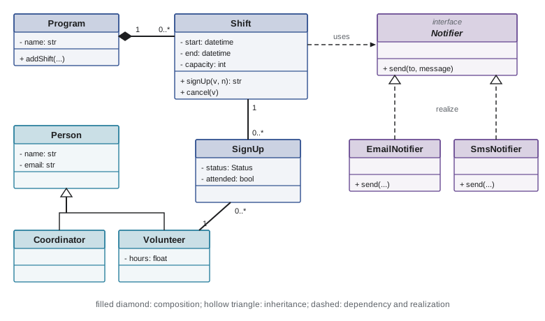
A class diagram shows classes as boxes with three compartments: the name, the attributes and the operations. Visibility is marked with + for public, - for private, # for protected and ~ for package. Attributes are written name: Type and operations name(parameters): ReturnType. Lines between classes show relationships, and their ends carry multiplicities such as 1, 0..1, * (many) or 1..*.
| Relationship | Notation | Meaning | In Python |
|---|---|---|---|
| Association | Solid line, optional arrow and multiplicities | Objects of one class know about objects of another | An attribute holding a reference or a collection |
| Aggregation | Hollow diamond at the whole | Whole and part, but the part can exist independently | A collection of references to shared objects |
| Composition | Filled diamond at the whole | Strong ownership; parts are created and destroyed with the whole | The whole creates and holds its parts |
| Generalization | Hollow triangle pointing to the superclass | Inheritance: the subclass is a kind of the superclass | class Volunteer(Person) |
| Realization | Dashed line with hollow triangle | A class implements an interface | A class satisfying a Protocol or ABC |
| Dependency | Dashed arrow | One class uses another temporarily, such as a parameter | A function parameter or local variable |
The distinction between aggregation and composition causes endless debate and matters less than it seems; many practitioners simply use plain associations unless ownership is important. What matters more is getting multiplicities right, because they become code and database constraints. A Shift with capacity and 0..* SignUps, each SignUp linking exactly one Volunteer to exactly one Shift, describes a many-to-many relationship with data of its own (the status), which in a database becomes a junction table and in code becomes a class.
from dataclasses import dataclass, field
from datetime import datetime
from typing import Protocol

class Notifier(Protocol):                 # an interface; realized by concrete notifiers
    def send(self, to: str, message: str) -> None: ...

class EmailNotifier:
    def send(self, to: str, message: str) -> None:
        print(f"email to {to}: {message}")

@dataclass
class Person:                             # generalization: Volunteer and Coordinator inherit
    name: str
    email: str

@dataclass
class Volunteer(Person):
    hours: float = 0.0

@dataclass
class SignUp:                             # association class: one volunteer on one shift
    volunteer: Volunteer
    status: str = "confirmed"

@dataclass
class Shift:
    start: datetime
    end: datetime
    capacity: int
    signups: list[SignUp] = field(default_factory=list)    # 0..* SignUp

    def sign_up(self, v: Volunteer, notifier: Notifier) -> str:   # dependency on Notifier
        confirmed = [s for s in self.signups if s.status == "confirmed"]
        status = "confirmed" if len(confirmed) < self.capacity else "waitlisted"
        self.signups.append(SignUp(v, status))
        notifier.send(v.email, f"You are {status} for {self.start:%a %d %b %H:%M}")
        return status

@dataclass
class Program:                            # composition: shifts belong to one program
    name: str
    shifts: list[Shift] = field(default_factory=list)

    def add_shift(self, start: datetime, end: datetime, capacity: int) -> Shift:
        s = Shift(start, end, capacity)
        self.shifts.append(s)
        return s

pantry = Program("Pantry")
sat = pantry.add_shift(datetime(2026, 11, 7, 9), datetime(2026, 11, 7, 12), capacity=1)
for who in (Volunteer("Ana", "ana@example.org"), Volunteer("Ben", "ben@example.org")):
sat.sign_up(who, EmailNotifier())email to ana@example.org: You are confirmed for Sat 07 Nov 09:00 email to ben@example.org: You are waitlisted for Sat 07 Nov 09:00
Sequence diagrams
A sequence diagram shows how objects interact in one scenario. Participants are arranged across the top, each with a dashed lifeline running down. Time flows downward. Solid arrows with filled heads are synchronous calls, open arrowheads are asynchronous messages, and dashed arrows are returns. Thin rectangles on a lifeline, called activations, show when that participant is working. Frames labeled alt, opt and loop show alternatives, optional parts and repetition. Sequence diagrams are excellent for designing an interaction before coding it, for explaining a protocol such as a login flow, and for checking that responsibilities are sensibly divided: if one participant does all the work and others merely pass data, the design may need rethinking.
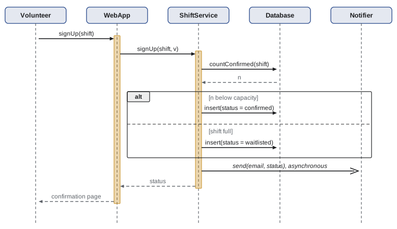
Sequence diagrams also work in reverse, as a debugging tool: recording which objects call which, in what order, produces the sequence that actually happens. The small tracer below does exactly that for the sign-up scenario, printing an indented call log that reads like a sequence diagram.
import functools

depth = 0
def traced(cls):
    """Wrap every public method so each call and return is printed with indentation."""
    for name, fn in list(vars(cls).items()):
        if callable(fn) and not name.startswith("_"):
            def wrap(fn=fn, name=name):
                @functools.wraps(fn)
                def inner(self, *args):
                    global depth
                    print("  " * depth + f"-> {cls.__name__}.{name}(" + ", ".join(map(repr, args)) + ")")
                    depth += 1
                    result = fn(self, *args)
                    depth -= 1
                    print("  " * depth + f"<- {cls.__name__}.{name} returns {result!r}")
                    return result
                return inner
            setattr(cls, name, wrap())
    return cls

@traced
class Database:
    def __init__(self): self.rows = {"sat-am": ["Ana"]}
    def confirmed(self, shift): return len(self.rows[shift])
    def insert(self, shift, who): self.rows[shift].append(who); return True

@traced
class Notifier:
    def send(self, who, text): return "queued"

@traced
class ShiftService:
    def __init__(self, db, notifier, capacity): self.db, self.n, self.cap = db, notifier, capacity
    def sign_up(self, shift, who):
        status = "confirmed" if self.db.confirmed(shift) < self.cap else "waitlisted"
        self.db.insert(shift, who)
        self.n.send(who, status)
        return status

ShiftService(Database(), Notifier(), capacity=1).sign_up("sat-am", "Ben")-> ShiftService.sign_up('sat-am', 'Ben')
-> Database.confirmed('sat-am')
<- Database.confirmed returns 1
-> Database.insert('sat-am', 'Ben')
<- Database.insert returns True
-> Notifier.send('Ben', 'waitlisted')
<- Notifier.send returns 'queued'
<- ShiftService.sign_up returns 'waitlisted'State machine diagrams
A state machine diagram, often called a statechart after David Harel's 1987 notation that UML adopted, shows the states an object can be in and the transitions between them. A filled circle marks the initial state and a circled dot the final state. Each transition is labeled event [guard] / action: when the event occurs and the guard condition is true, the action happens and the object moves to the new state. State machines are ideal for objects with lifecycles and rules about what may happen when, such as orders, accounts, documents in a review workflow, network connections, and here, a sign-up that may be confirmed, waitlisted, canceled, attended or marked as a no-show.
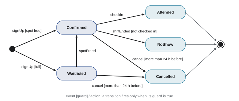
State machines translate directly into code, and doing so explicitly prevents a whole class of bugs in which an object reaches an impossible state, such as a canceled sign-up being checked in. A transition table makes the allowed moves data rather than scattered if statements, and every transition in the diagram becomes a test.
class InvalidTransition(Exception):
    pass

# (state, event) -> new state; guards are checked in fire()
TRANSITIONS = {
    ("new", "sign_up_free"): "confirmed",
    ("new", "sign_up_full"): "waitlisted",
    ("waitlisted", "spot_freed"): "confirmed",
    ("confirmed", "cancel"): "cancelled",
    ("waitlisted", "cancel"): "cancelled",
    ("confirmed", "check_in"): "attended",
    ("confirmed", "shift_ended"): "no_show",
}

class SignUp:
    def __init__(self):
        self.state = "new"

    def fire(self, event, hours_before=None):
        if event == "cancel" and hours_before is not None and hours_before < 24:
            raise InvalidTransition("cancel guard failed: less than 24 h before the shift")
        key = (self.state, event)
        if key not in TRANSITIONS:
            raise InvalidTransition(f"{event!r} not allowed in state {self.state!r}")
        self.state = TRANSITIONS[key]
        return self.state

s = SignUp()
print(s.fire("sign_up_full"), "->", s.fire("spot_freed"), "->", s.fire("check_in"))
for events in (["sign_up_free", "cancel", "check_in"], ["sign_up_free"]):
    s = SignUp()
    try:
        for e in events:
            s.fire(e, hours_before=48)
        s.fire("cancel", hours_before=3)
    except InvalidTransition as exc:
print("rejected:", exc)waitlisted -> confirmed -> attended rejected: 'check_in' not allowed in state 'canceled' rejected: cancel guard failed: less than 24 h before the shift
Activity diagrams
An activity diagram models a workflow: rounded rectangles are actions, diamonds are decisions and merges, thick bars are forks and joins for parallel paths, and swimlanes can show which actor or system does each action. Activity diagrams are close relatives of flowcharts and are useful for describing business processes before automating them, such as how a new volunteer goes from application to first shift (application, then a reference check and orientation in parallel, then a decision on minors needing parental consent, then activation). They help find steps that could run in parallel, handoffs where work waits, and decisions that nobody owns.
Component and deployment diagrams
Component diagrams show the major parts of a system and the interfaces between them, using provided interfaces (drawn as small circles, sometimes called lollipops) and required interfaces (half circles, or sockets). Deployment diagrams show the nodes, such as servers, containers, phones or cloud services, and which components run on each, with the communication paths between them. These diagrams describe architecture, the subject of lesson 6. Many teams now prefer the simpler C4 model by Simon Brown, which describes a system at four zoom levels (context, containers, components and code) with plain boxes and arrows, and use UML only for the detailed code level.
Modeling in practice
A few habits make models useful. Draw a diagram to answer a specific question, and include only what helps answer it; a class diagram with every attribute of fifty classes communicates nothing. Name things in the language of the domain, the same words the users and the code use, an idea that Eric Evans's domain-driven design calls the ubiquitous language. Keep long-lived diagrams as text in the repository, using tools such as PlantUML or Mermaid, so that they are versioned and reviewed alongside the code and can be regenerated. And remember that a diagram nobody updates becomes misleading; it is better to have three accurate diagrams than thirty stale ones.
@startuml
' PlantUML source for the sign-up state machine, kept in the repository
' next to the code and rendered to an image by the build
[*] --> Confirmed : signUp [spot free]
[*] --> Waitlisted : signUp [full]
Waitlisted --> Confirmed : spotFreed
Confirmed --> Cancelled : cancel [> 24 h before]
Waitlisted --> Cancelled : cancel [> 24 h before]
Confirmed --> Attended : checkIn
Confirmed --> NoShow : shiftEnded [not checked in]
Attended --> [*]
NoShow --> [*]
Cancelled --> [*]
@enduml
Worked problem
From a description to a class diagram
Model this description: "A food bank runs several programs. Each program has shifts. A volunteer can sign up for many shifts and a shift can have many volunteers, up to its capacity. For each sign-up we record whether the volunteer attended. Coordinators manage one or more programs." Identify classes, key attributes, relationships and multiplicities.
Show solution
- Nouns suggest classes: FoodBank, Program, Shift, Volunteer, Coordinator, SignUp. "Attended" is an attribute of the sign-up, not of the volunteer or the shift.
- FoodBank 1 composes 1..* Program; Program 1 composes 0..* Shift (shifts do not exist without their program).
- Volunteer *–* Shift with data of its own becomes an association class SignUp (attended: bool, status: Status), with Shift 1 to 0..* SignUp and Volunteer 1 to 0..* SignUp. Capacity is an attribute of Shift; the rule "up to its capacity" is a constraint, written {count of confirmed sign-ups <= capacity}.
- Coordinator 1..* to 1..* Program ("manages"). Volunteer and Coordinator may generalize to Person if they share attributes such as name and email.
Answer: Six classes, two compositions, an association class for sign-ups, a many-to-many "manages" association and an optional Person superclass. The capacity rule appears as a constraint, and every multiplicity will become code or a database constraint.
Worked problem
Finding a missing transition
Testers report that a coordinator cannot cancel a shift that has been called off because of a snowstorm: all its sign-ups are stuck in Confirmed. Using the state machine above, what is missing and how would you add it?
Show solution
- The only way out of Confirmed is cancel by the volunteer (with a 24-hour guard), check-in or the shift ending.
- Add an event shiftCancelled that moves both Confirmed and Waitlisted to a new state CancelledByOrganizer, with an action that notifies the volunteer.
- Add the two entries to the transition table and a test for each, and check that hours are not credited for canceled shifts.
Answer: A missing event and state. Drawing the state machine makes such gaps visible; encoding it as a table makes adding the fix a small, testable change.
Common mistakes
MistakeDrawing every class, attribute and method in one huge diagram.
InsteadModel to answer a question; show only the elements relevant to it.
MistakeUsing UML as a blueprint nobody maintains.
InsteadKeep a few diagrams that matter, preferably as text in the repository, and let code and tests be the detailed truth.
MistakeConfusing a class diagram's associations with database foreign keys only.
InsteadAssociations describe object references; they map to foreign keys or junction tables, but also to attributes and collections in code.
MistakeIgnoring multiplicities.
InsteadMultiplicities become constraints in code and databases; getting 1 versus 0..1 wrong causes real bugs.
MistakeImplementing object lifecycles with scattered if statements.
InsteadDraw the state machine and encode it as a transition table so impossible transitions are rejected and every transition is tested.
Summary and key terms
- A model simplifies a system to support reasoning and communication; UML, standardized by the OMG (current version 2.5.1), is the standard notation.
- UML can be used as a sketch, a blueprint or a programming language; most agile teams sketch and keep only diagrams worth maintaining.
- Use case diagrams scope a system by actors and goals; class diagrams show structure with associations, aggregation, composition, generalization, realization and dependency.
- Sequence diagrams show messages over time for one scenario, with alt, opt and loop frames.
- State machine diagrams show states, events, guards and actions; encoding them as transition tables prevents impossible states.
- Activity diagrams model workflows with decisions and parallel paths; component and deployment diagrams, or the C4 model, describe architecture.
- Diagrams kept as text (PlantUML, Mermaid) can be versioned and reviewed with the code.
- Model
- A simplified representation of a system that shows some aspects and hides others.
- UML
- The Unified Modeling Language, a standard notation for software models.
- Class diagram
- A diagram of classes, their attributes and operations, and relationships.
- Multiplicity
- The number of objects that may take part in an association, such as 1, 0..1 or *.
- Composition
- A strong whole–part relationship in which parts live and die with the whole.
- Sequence diagram
- A diagram of the messages exchanged between participants over time in one scenario.
- Lifeline
- The vertical dashed line representing a participant over time in a sequence diagram.
- State machine diagram
- A diagram of an object's states and the transitions triggered by events.
- Guard
- A condition that must be true for a transition to fire.
- C4 model
- A lightweight way to describe architecture at context, container, component and code levels.
Practice problems
Work each problem on paper first, then reveal the answer to check.
What do +, - and # mean before an attribute in a class diagram?
Show answer
Public, private and protected visibility.
Model "an order has one or more order lines; lines cannot exist without their order". Which relationship and multiplicities?
Show answer
Composition from Order (1) to OrderLine (1..*).
When is an association class needed?
Show answer
When a many-to-many relationship has data of its own, such as the status of a sign-up.
In a sequence diagram, what does a dashed arrow usually show?
Show answer
A return message.
Write the transition label for "on cancel, if more than 24 hours remain, refund the deposit".
Show answer
cancel [hoursBefore > 24] / refundDeposit()
Name two kinds of bug a state machine table prevents.
Show answer
Reaching impossible states (checking in a canceled sign-up) and missing transitions being handled inconsistently in different places.
Which diagram would you draw to explain how a login with single sign-on works?
Show answer
A sequence diagram of the browser, application and identity provider.
What are the four levels of the C4 model?
Show answer
Context, containers, components and code.
Give one advantage of keeping diagrams as PlantUML or Mermaid text.
Show answer
They are versioned and reviewed with the code, show meaningful diffs, and can be regenerated automatically.
Fowler describes three modes of using UML. Name them.
Show answer
Sketch, blueprint and programming language.
Lesson quiz · 5 questions
Score 60% or more to complete this lesson.
Create a free account to save your progress, take quizzes and earn a certificate.