
CIV-341 · Lesson 12 of 12 · 21 min
Foundation design capstone: the fleet storage building
The last lesson brings the course together in the foundation design package for the Kestrel Bay site: the fleet storage building on driven piles, the garage on preloaded ground with spread footings, and the pump station, whose concrete box must neither float nor be lifted by the artesian till. Dr. Kowalczyk's team must produce the foundation design report, with the design basis, the calculations summarized for each limit state, the drawings and specifications that the contractor will price, and the inspection and monitoring plan that will confirm the design in the field. Owen prepares the calculations; Sofia's final script checks them in one place.
The design basis
A design report begins by stating its basis, so that anyone who reads it later knows what was assumed. For Kestrel Bay, that means:
- Codes and standards: the Minnesota State Building Code (based on the IBC) and ASCE 7 for loads, allowable stress design for geotechnical capacity, ACI 318 and AISC 360 for the concrete and steel elements, and ASTM standards for load testing.
- The ground model: the stratigraphy, groundwater and design parameters of the CIV-340 soils report, supplemented by the four new boreholes and two CPTs at the fleet building, which confirmed the same sequence with the till 4.0 to 4.5 m (13 to 15 ft) thick over rock.
- The loads: column loads from the structural engineer, separated into dead, live, snow, wind and crane components, with the sustained part identified for settlement and drag.
- Performance criteria: total settlement of the fleet building not more than 25 mm (1 in.), angular distortion not more than 1/1,000 along the crane rails; for the garage, 1/500 between adjacent columns; for the pump station, a factor of safety against flotation of at least 1.25 at the design high water level.
The fleet storage building
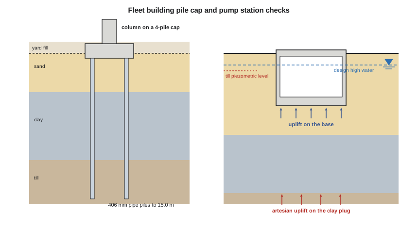
The fleet building is supported on closed-end steel pipe piles, 16 in. diameter with a 0.5 in. wall and a reinforced conical toe, driven to a toe level of about 49 ft in the dense till and filled with concrete. Each interior column bears on a cap with four piles at 4 ft centers. The design summary is:
| Check | Lesson | Result |
|---|---|---|
| Axial capacity, single pile | 9 | 401 kips ultimate by static analysis |
| Static load test | 11 | Davisson 443 kips; capacity confirmed, FS = 2 |
| Column ASD | 9, 12 | P = 712 kips incl. cap vs 4 × 200 = 802 kips |
| Group and block | 10 | Sum of piles governs; block about twice as strong |
| Drag force and downdrag | 10 | Maximum load 278 kips; settlement at the neutral plane < 0.05 in. |
| Group settlement | 10 | About 0.4 in. |
| Lateral | 11 | Fixed-head deflection 0.07 in. at 7 kips; allowable 46 kips |
Because the piles end in till that does not settle significantly, the building is effectively isolated from the consolidation caused by the yard fill. The ground floor slab is a different matter: placed on the fill over the clay, it would settle with the yard. Dr. Kowalczyk and the structural engineer choose a structural slab spanning between the pile caps on grade beams, with a void former beneath it, rather than a slab-on-grade, because the fleet building floor carries loaded trucks and must remain level at the doors and the crane rail supports. The aprons outside the doors are designed as hinged approach slabs that can rotate as the yard settles.
The garage
The garage foundations are the spread footings designed in CIV-330, founded at 5 ft on the sand, on ground preloaded with 8 ft of sand for at least three months with prefabricated vertical drains at 5 ft spacing. The bearing check governed by the clay gives a factor of safety of 4.3, the immediate settlement in the sand is 0.4 to 0.8 in., and the consolidation settlement after preloading is about 1.2 in. at the interior footings, with an angular distortion of about 1/880. The preload may be removed when settlement plates show that the settlement has leveled off at about 90 % of the predicted final value and the piezometers in the clay show that the excess pore pressure has fallen correspondingly.
The pump station
The pump station is a reinforced concrete box 20 ft square in plan, with its base at 15 ft below grade in the sand. Near B-4 the sand extends to 23 ft and the clay to 39 ft, over the artesian till. Two checks control the design. The first is flotation: when the station is empty for maintenance and the water table is high, the uplift of the groundwater on the base must not exceed the weight of the structure with a margin. The second is the uplift of the clay plug beneath the station by the artesian pressure in the till, which CIV-340 found critical during excavation, with a factor of safety of 1.34, and which the completed structure relieves by adding its weight.
Worked problem
Flotation of the empty pump station
The box has a 2.5 ft base, 1.33 ft walls rising 1 ft above grade and a 1 ft roof, all of concrete at 150 pcf. Find its weight and the factor of safety against flotation with the design high water level 3 ft below grade.
Show solution
- Volume of concrete:
- \[V = 20^2(2.5) + 4(18.67)(1.33)(15 - 2.5 + 1) + 20^2(1) = 1000 + 1341 + 400 = 2741\ \text{ft}^3\]
- \[W = 0.150(2741) = 411\ \text{kips}\]
- Uplift on the base, with 12 ft of water above it:
- \[U = 0.0624(15 - 3)(400) = 300\ \text{kips} \qquad FS = \frac{411}{300} = 1.37\]
Answer: The factor of safety exceeds the 1.25 required, without counting the friction of the soil on the walls or the weight of the pumps, which give additional margin. If the margin had been inadequate, the base slab could have been extended beyond the walls to engage the weight of the soil above the extension, or tension piles or anchors added.
Sofia's script assembles the column check for the fleet building and completes the pump station checks: flotation for normal and high water, uplift of the clay plug during and after construction, and the rebound of the clay caused by the net unloading.
# Capstone: foundation design summary for the fleet storage building and checks of the pump station
from math import pi, sqrt, atan2, log10
# --- fleet storage building, typical interior column on four 16 in. pipe piles
D, L, W_cap = 425.0, 250.0, 37.0                    # kips
Ps = D + W_cap + L
Qu, FS = 401.0, 2.0                                  # static analysis, confirmed by the static test (Davisson 443 kips)
n = 4
print(f"Column: Ps = {Ps:.0f} kips; {n} piles x Qu/FS = {n}*{Qu/FS:.1f} = {n*Qu/FS:.0f} kips "
      f"-> utilization {Ps/(n*Qu/FS):.2f}")
print(f"Drag (lesson 10): maximum load in a pile 278 kips vs structural design strength about 1,600 kips; "
      f"settlement at the neutral plane under 0.05 in.")
print(f"Lateral: 7 kips service per pile, fixed-head deflection 0.07 in.; allowable fixed-head 46 kips")
print(f"Settlement of the group: 0.37 in. below the equivalent footing + 0.04 in. shortening = {0.37 + 0.04:.2f} in.\n")

# --- pump station: a 20 ft square concrete box with its base at 15 ft (B-4: sand to 23 ft, clay to 39 ft)
B, z_base, t_base, t_wall, t_roof, gc = 20.0, 15.0, 2.5, 1.33, 1.0, 150.0
V = B*B*t_base + 4*(B - t_wall)*t_wall*(z_base - t_base + 1.0) + B*B*t_roof
W = V*gc/1000; A = B*B
for zw, case in ((8.0, 'normal water table 8 ft'), (3.0, 'design high water 3 ft')):
    U = 62.4*(z_base - zw)*A/1000
    print(f"Flotation, {case}: W = {W:.0f} kips, U = {U:.0f} kips, FS = W/U = {W/U:.2f}")
# uplift of the clay plug by the artesian till (piezometric level 5 ft below grade), at the base of the clay
u_till = 62.4*(39.0 - 5.0)
during = 126.0*(23.0 - z_base) + 115.0*(39.0 - 23.0)  # cofferdam dewatered to the base, before the structure
after = during + W*1000/A
print(f"Basal uplift at 39 ft: u = {u_till:,.0f} psf; FS during excavation {during/u_till:.2f}, "
      f"after construction {after/u_till:.2f}")
def corner(a, b, z):
    m, nn = a/z, b/z; s = m*m + nn*nn + 1
    return (2*m*nn*sqrt(s)/(s + m*m*nn*nn)*(s + 1)/s + atan2(2*m*nn*sqrt(s), s - m*m*nn*nn))/(4*pi)
removed = 115.0*8.0 + 126.0*(z_base - 8.0)
q_un = removed - W*1000/A
heave = 0.0; dz = 1.6
for k in range(10):                                  # clay from 23 to 39 ft in 1.6 ft sublayers
    z = 23.0 + dz*(k + 0.5)
    s0 = 115.0*8 + 126.0*15 + 115.0*(z - 23.0) - (62.4*15 + (u_till - 62.4*15)*(z - 23.0)/16.0)
    ds = 4*q_un*corner(B/2, B/2, z - z_base)
    heave += dz*0.047/2.06*log10(s0/(s0 - ds))
print(f"Net unloading {q_un:,.0f} psf (soil removed {removed:,.0f}, structure {W*1000/A:,.0f}); clay rebound {12*heave:.2f} in.")Column: Ps = 712 kips; 4 piles x Qu/FS = 4*200.5 = 802 kips -> utilization 0.89 Drag (lesson 10): maximum load in a pile 278 kips vs structural design strength about 1,600 kips; settlement at the neutral plane under 0.05 in. Lateral: 7 kips service per pile, fixed-head deflection 0.07 in.; allowable fixed-head 46 kips Settlement of the group: 0.37 in. below the equivalent footing + 0.04 in. shortening = 0.41 in. Flotation, normal water table 8 ft: W = 411 kips, U = 175 kips, FS = W/U = 2.35 Flotation, design high water 3 ft: W = 411 kips, U = 300 kips, FS = W/U = 1.37 Basal uplift at 39 ft: u = 2,122 psf; FS during excavation 1.34, after construction 1.83 Net unloading 774 psf (soil removed 1,802, structure 1,028); clay rebound 0.37 in.
Reading the results
The fleet building column has a utilization of 0.89 with four piles and the test-confirmed factor of safety, so the four-pile cap stands with a reasonable margin for later changes in the loads. The pump station has a factor of safety against flotation of 2.35 at the normal water table and 1.37 at the design high water. The uplift of the clay plug, 1.34 during excavation, rises to 1.83 once the structure is in place, so the critical period is the few weeks between reaching the base and casting the slab, when the relief wells and the piezometer trigger levels from CIV-340 must be in operation. The net unloading of 774 psf, the soil removed less the weight of the structure, causes a rebound of about 0.4 in. in the clay, most of it during the excavation.
Owen notices that the rebound and the later settlement of the pump station differ from those of the pipes connecting it to the garage and the yard drains. The connections are therefore made with flexible couplings designed for 25 mm (1 in.) of differential movement.
Specifications, inspection and monitoring
A foundation design is only as good as its execution. The report includes a construction section, and the specifications turn it into contractual requirements:
- Pile installation: the hammer approved on the basis of a wave equation analysis; the driving criterion, a minimum toe level in the till and a minimum final set, established on the test pile; records of every pile; redriving of any pile heaved by more than a few millimeters by adjacent driving; internal inspection of each pipe before concrete is placed.
- Testing: a static load test on the test pile before production; dynamic testing at the end of driving and on restrike of the test pile and of at least 5 % of production piles.
- Preloading: placement of the preload in lifts, settlement plates and vibrating wire piezometers, and a hold until the agreed criteria are met.
- Pump station: sheet piling to the specified tip, a piezometer in the till inside the cofferdam with alert and action levels, relief wells ready before excavation reaches the clay, and no over-excavation.
- Inspection of footing bases by the geotechnical engineer before concrete is placed, and protection of exposed soil from water and frost.
- Monitoring after construction: settlement points on selected garage and fleet building columns, read monthly for the first year and quarterly for two more, compared with the predictions.
Looking back
Owen reflects on what the course has taught him. The bearing calculations were the easy part: almost every bearing check passed with a comfortable margin. The decisions that mattered were about deformation and water. The thin sand over the clay made the garage settle unevenly; preloading, not stronger footings, solved it. The heavy fleet building needed piles because of settlement, not bearing, and the piles had to end in the till so that the yard fill would not drag them down. The artesian till, discovered by a single piezometer, controlled the pump station. And at each step, a cheap investigation or test bought a large saving or avoided a serious risk: a CPT that calibrated the clay strength, a load test that saved two piles under every column, a piezometer that revealed the uplift.
Dr. Kowalczyk's last comment is the one that Terzaghi and Peck would have made. Every number in the report is an estimate, and the ground will not read it. The design is complete only when construction confirms that the ground behaves as predicted, and the monitoring plan is the part of the report that makes sure it does.
Practical points
- State the design basis: codes, ground model, loads and performance criteria.
- Summarize every limit state for each structure, with its result and the lesson or calculation behind it.
- Identify the critical construction stages, such as excavation to the base of the pump station, and protect them.
- Turn recommendations into specifications with measurable acceptance criteria.
- Plan monitoring that will reveal whether the predictions were right while there is still time to act.
Common mistakes
MistakeStopping the design at the bearing calculation.
InsteadCheck settlement, drag, uplift, flotation and construction stages.
MistakeChecking flotation only at the normal water table.
InsteadUse the design high water level and the empty condition.
MistakeTreating the end of construction as the most critical moment for every structure.
InsteadFor the pump station, the critical moment is excavation before the slab is cast.
MistakeWriting recommendations that cannot be checked on site.
InsteadGive measurable criteria for driving, testing, preload removal and monitoring.
Summary and key terms
- The design basis records the codes, ground model, loads and performance criteria.
- Fleet building: four 16 in. pipe piles per column to the till; utilization 0.89 with FS = 2 after a static test; drag force harmless; settlement about 0.4 in.
- Garage: spread footings on preloaded ground meet the distortion limit.
- Pump station: flotation FS 1.37 at high water; clay plug uplift FS 1.34 during excavation, 1.83 after construction.
- Specifications, inspection and monitoring confirm the design in the field.
- Design basis
- The statement of codes, data, loads and criteria on which a design rests.
- Flotation
- The uplift of a buried structure by groundwater pressure when its weight is insufficient.
- Basal uplift
- Heave or rupture of the soil at the base of an excavation by pore pressure from below.
- Rebound
- Expansion of soil when the stress on it is reduced, as by excavation.
- Driving criterion
- The required final set or blow count and toe level for accepting a driven pile.
- Structural slab
- A floor slab supported on the foundations rather than on the ground.
- Approach slab
- A slab that bridges between a structure and adjacent settling ground.
- Monitoring plan
- The specified measurements that compare actual behavior with predictions during and after construction.
Practice problems
Work each problem on paper first, then reveal the answer to check.
An empty concrete tank weighs 200 kips and has a base area of 270 ft², 10 ft below the design high water. Find the factor of safety against flotation.
Show answer
\(U = 0.0624(10)(270) = 168\) kips; \(FS = 1.19\), below 1.25.
Give two ways to increase the safety of that tank against flotation.
Show answer
Extend the base slab beyond the walls to engage soil weight, thicken the base, add tension piles or anchors, or install relief or underdrain systems.
Why is the excavation stage more critical than the completed pump station for basal uplift?
Show answer
The weight of the structure is not yet in place to resist the artesian pressure.
Why does the fleet building have a structural floor slab rather than a slab-on-grade?
Show answer
The yard fill will consolidate the clay, and a slab on grade would settle relative to the pile-supported building.
Lesson quiz · 5 questions
Score 60% or more to complete this lesson.
Create a free account to save your progress, take quizzes and earn a certificate.