
CIV-341 · Lesson 1 of 12 · 22 min
The foundation design process and limit states
Soil mechanics, the subject of CIV-340, explains how soil carries stress, how water moves through it and how it compresses and fails. Foundation engineering puts that knowledge to work. Its question is practical: what should the structure stand on, how big must it be, how deep must it go, and how will it behave over the life of the building? This course answers that question for the buildings of the Kestrel Bay operations center in Duluth, from the spread footings of the garage designed in CIV-330 to the piles that will carry a new fleet storage building, and finishes with a complete foundation design package. This first lesson sets out the design process, the people involved and the two design formats, allowable stress design and load and resistance factor design, that every later calculation will use.
What a foundation must do
A foundation transfers the loads of a structure into the ground. To do that successfully it has to satisfy three requirements at the same time. First, the ground must not fail: the soil beneath and around the foundation must not shear, punch or slide under the loads, with an adequate margin for uncertainty. Second, the foundation must not move too much: total settlement, differential settlement between parts of the structure, tilt and lateral movement must stay within what the structure, its finishes and its services can tolerate. Third, the foundation itself must be strong and durable: the concrete, steel or timber in it must carry the forces it receives, resist frost, sulfates, corrosion and abrasion, and be buildable with the equipment and methods available on the site.
A fourth requirement is often forgotten until it causes trouble: the foundation must not harm its neighbors. Excavations undermine adjacent footings, dewatering consolidates clays under nearby buildings, pile driving shakes sensitive equipment and heaves the ground, and new loads drag down existing piles. A good foundation design considers the effect of the work on everything around it, as well as the effect of the ground on the new structure.
The design process
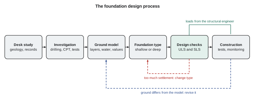
Foundation design is iterative. It begins long before the structural drawings are finished and continues until the last pile is accepted in the field. The main stages are these.
- Desk study. Before drilling a single hole, the geotechnical engineer reads the geological maps, previous investigations on or near the site, air photos and records of fill or old structures. At Kestrel Bay the desk study showed glacial lake clays over till, with a known artesian aquifer in the till near the lake.
- Site investigation. Boreholes, sampling, in-situ tests such as the SPT, CPT and field vane, groundwater measurements and laboratory tests establish the ground model. Lesson 2 reviews how to plan and interpret an investigation for foundation design.
- Ground model and design parameters. The engineer turns the factual data into a model: the layers, their thicknesses, the groundwater conditions and characteristic values of strength, stiffness and compressibility for each layer.
- Selection of the foundation type. Shallow foundations (spread footings, strip footings, combined footings and mats) are considered first, because they are usually the cheapest. Deep foundations (driven piles, drilled shafts, helical piles and micropiles) are used when shallow foundations would fail, settle too much or be impractical.
- Design calculations. Bearing resistance, settlement, sliding, uplift, lateral resistance and the structural design of the foundation elements are checked for all relevant load cases.
- Interaction with the structural engineer. The geotechnical engineer gives bearing resistances, settlement predictions and spring stiffnesses; the structural engineer gives loads and tolerances. The loads change as the structure develops, and the foundation design changes with them.
- Construction and verification. Field inspection confirms that the ground matches the model: the founding soil is what was expected, the piles reach the required set or depth, and load tests confirm the predicted resistance. Monitoring of settlement and pore pressures may continue for years.
Who does what
On a building project in Minnesota, the structural engineer of record designs the foundation elements as structural members, while the geotechnical engineer, a licensed professional engineer with expertise in soils, provides the geotechnical design: the allowable bearing pressures, the settlement predictions, the pile capacities and the construction recommendations. The responsibilities are set out in the contracts and in the special inspection requirements of the building code. Dr. Lena Kowalczyk, P.E., the geotechnical engineer who wrote the soils report in CIV-340, now leads the foundation design for Kestrel Bay Engineering, with Owen Lachance, EI, doing the calculations and Sofia Martel, a co-op student, writing the Python scripts that check them.
Uncertainty in geotechnical design
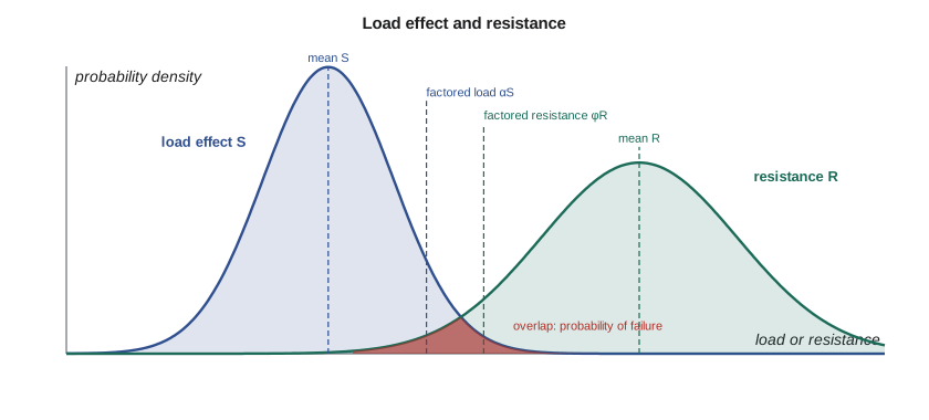
Structural engineers work with materials whose properties are specified, manufactured and tested: a steel grade has a guaranteed minimum yield strength, and concrete is tested in cylinders from every pour. Geotechnical engineers work with materials that nature made. The soil under a footing was deposited thousands of years ago and has been sampled at a few points, perhaps a few liters of soil for a site of thousands of cubic meters. Its properties vary from place to place, and the methods used to calculate bearing resistance and settlement are themselves approximate.
That uncertainty is the reason for safety margins. It is also why geotechnical design relies so heavily on judgment, experience and observation. Karl Terzaghi, who founded soil mechanics in the 1920s, and Ralph Peck, his colleague, insisted that calculations be checked against field behavior, and Peck's observational method, in which a design is adapted during construction according to what monitoring reveals, remains an important tool when the ground is too uncertain to design with confidence in advance.
Limit states
A limit state is a condition beyond which the foundation no longer fulfills its purpose. Modern codes group limit states into two families.
Ultimate limit states (ULS) involve collapse or failure: bearing failure of the ground, sliding, overturning, uplift of a buoyant structure, failure of a pile in compression or tension, or structural failure of a footing or pile. For these, the design must give a high level of safety, because failure could cost lives.
Serviceability limit states (SLS) involve loss of function without collapse: excessive total or differential settlement, tilt, vibration or lateral movement. They are checked with unfactored, specified loads, because they concern the everyday behavior of the structure. In most foundation designs on soil, serviceability rather than bearing failure governs the size of the foundation.
In the United States, the International Building Code (IBC), adopted in Minnesota as part of the state building code, gives the general requirements for foundations in its Chapter 18. For building foundations, most geotechnical practice still uses allowable stress design (ASD): the ultimate capacity is divided by a global factor of safety, and the result is compared with the service loads. Load and resistance factor design (LRFD), in which factored loads are compared with a factored resistance, is used for bridge foundations under the AASHTO LRFD Bridge Design Specifications and increasingly for buildings. The two formats are:
where \(Q_u\) is the ultimate capacity, \(FS\) is the factor of safety and \(\gamma_i Q_i\) are the factored loads, such as \(1.2D + 1.6L\) from ASCE 7. Typical factors of safety in building practice are 3 for the bearing capacity of shallow foundations, 1.5 for sliding and overturning, and 2 to 3 for piles, with the lower value permitted when capacity is confirmed by load tests. In the AASHTO LRFD specifications, typical resistance factors are about 0.45 to 0.50 for the bearing resistance of spread footings and 0.35 to 0.45 for pile resistance calculated by static analysis, rising to about 0.75 when a sufficient number of static load tests are performed. Settlement is checked separately at the service level, with unfactored loads.
Why factors of safety are large
A factor of safety of 3 on bearing capacity seems generous compared with the factors of about 1.5 implied in structural steel design. It is not. The bearing capacity theory of lesson 3 is sensitive to the friction angle: a change of two degrees changes the bearing capacity of a footing on sand by about 30 %. The friction angle itself is usually estimated from SPT or CPT correlations with a scatter of several degrees. The large factor covers the uncertainty in the parameters, the approximations in the theory and the fact that the bearing pressure that causes failure is usually accompanied by settlements far larger than any structure could tolerate. A factor of 3 on bearing also tends to keep settlements of footings on sand within acceptable limits, which is one reason it has survived so long in practice.
The LRFD format does not remove the need for judgment. A resistance factor of 0.45 applied with the ASCE 7 load factors gives an equivalent global factor of safety of about 2.7 to 3.2, depending on the ratio of live to dead load, close to the traditional value of 3. The load factors carry part of the uncertainty that used to be lumped into the single factor of safety.
The garage footing as a first example
CIV-330 designed the interior footings of the garage as 10 ft squares founded 5 ft below grade, for column loads of \(D = 380\) kips and \(L = 160\) kips. The structural design used an allowable bearing pressure of 5.5 ksf given in a preliminary report. The soils report of CIV-340 then found a sand layer only 8 ft thick below the footings, over a soft to firm clay. Dr. Kowalczyk asks Owen to start the foundation design from the beginning: what bearing capacity does the footing need, and does the ground provide it?
Worked problem
Required bearing resistance of the interior footing
The 10 ft square footing weighs 37.5 kips and carries 28.8 kips of backfill. Find the service and factored gross bearing pressures, and the ultimate bearing capacity needed with \(FS = 3\) and with \(\phi = 0.45\).
Show solution
- Total dead load, including the footing and the backfill:
- \[D = 380 + 37.5 + 28.8 = 446.3\ \text{kips}\]
- Service load and pressure (ASD):
- \[P_s = 446.3 + 160 = 606.3\ \text{kips} \qquad q = \frac{606.3}{100} = 6.06\ \text{ksf}\]
- Required ultimate bearing capacity with \(FS = 3\):
- \[q_u \ge 3(6.06) = 18.2\ \text{ksf}\]
- With LRFD: \(P_u = 1.2(446.3) + 1.6(160) = 791.6\) kips, \(q_u \ge 7.92/0.45 = 17.6\) ksf.
Answer: The ground must provide an ultimate bearing capacity of at least 18.2 ksf. Lessons 3 and 4 will show that the sand alone could provide far more, but the clay beneath it reduces the capacity to about 26 ksf, still adequate.
Sofia's script repeats the calculation and tabulates the equivalent global factor of safety of the factored format for different ratios of live to dead load.
# Allowable stress and LRFD checks of the interior garage footing (ASCE 7 load combinations)
D_col, L_col = 380.0, 160.0           # service column loads (kips)
W_ftg, W_fill = 37.5, 28.8            # footing and backfill over it (kips)
B = 10.0                              # footing width (ft)
A = B * B
D = D_col + W_ftg + W_fill
Ps = D + L_col                        # ASD combination D + L
Pu = 1.2 * D + 1.6 * L_col            # LRFD combination
print(f"Dead load incl. footing and fill D = {D:.1f} kips, live L = {L_col:.0f} kips")
print(f"ASD service load   Ps = D + L        = {Ps:.1f} kips -> q = {Ps/A*1000:,.0f} psf")
print(f"LRFD factored load Pu = 1.2D + 1.6L  = {Pu:.1f} kips -> qu = {Pu/A*1000:,.0f} psf")
print(f"ASD with FS = 3: required ultimate bearing capacity >= {3*Ps/A*1000:,.0f} psf")
for phi in (0.45, 0.50):
    print(f"LRFD with phi = {phi:.2f}: required ultimate bearing capacity >= {Pu/A/phi*1000:,.0f} psf")
print("\nEquivalent global factor of safety of the LRFD format, phi = 0.45")
print(" L/D   FS = (1.2 + 1.6 L/D) / (phi (1 + L/D))")
for r in (0.0, 0.25, 0.36, 0.75, 1.0, 1.5):
    fs = (1.2 + 1.6 * r) / (0.45 * (1 + r))
print(f"{r:4.2f} {fs:5.2f}")Dead load incl. footing and fill D = 446.3 kips, live L = 160 kips ASD service load Ps = D + L = 606.3 kips -> q = 6,063 psf LRFD factored load Pu = 1.2D + 1.6L = 791.6 kips -> qu = 7,916 psf ASD with FS = 3: required ultimate bearing capacity >= 18,189 psf LRFD with phi = 0.45: required ultimate bearing capacity >= 17,590 psf LRFD with phi = 0.50: required ultimate bearing capacity >= 15,831 psf Equivalent global factor of safety of the LRFD format, phi = 0.45 L/D FS = (1.2 + 1.6 L/D) / (phi (1 + L/D)) 0.00 2.67 0.25 2.84 0.36 2.90 0.75 3.05 1.00 3.11 1.50 3.20
Reading the results
The equivalent factor of safety rises from 2.67 for a pure dead load to 3.20 for a live load one and a half times the dead load. For the garage footing, with \(L/D = 0.36\), it is about 2.9, so ASD with \(FS = 3\) and LRFD with \(\phi = 0.45\) demand almost the same ultimate capacity, 18.2 and 17.6 ksf. What matters is that the engineer uses one format consistently, with the load factors and resistance or safety factors that belong together. Mixing a factor of safety with factored loads double-counts the margin; mixing a resistance factor with service loads leaves too little.
Serviceability criteria
For the serviceability limit state, the engineer needs to know what movement the structure can tolerate. That depends on the structure. A steel portal-frame warehouse with metal cladding can accept differential settlements that would crack the brick walls of an office building. Lesson 6 gives the widely used criteria for angular distortion and total settlement. At this stage, Owen notes the targets agreed with the structural engineer for the garage: total settlement of footings not more than about 50 mm, and angular distortion between adjacent columns not more than 1/500, because the garage has a concrete flat plate and masonry partitions.
Serviceability also includes things other than settlement: the heave of footings on frost-susceptible soil, the swelling of expansive clays, vibrations from machinery and the movement of a basement wall. Many foundation failures in practice are serviceability failures caused by water: poor drainage, a broken pipe, or a change in the water table that the design did not anticipate.
Practical points
- Start every foundation design with the ground model and the loads; check that both are current.
- Check ultimate limit states with factored loads and factored resistances, or with service loads and a factor of safety, but never mix the two formats.
- Check serviceability with unfactored, specified loads, and agree the tolerable movements with the structural engineer.
- Include the weight of the footing and the backfill in the loads when working with gross pressures.
- Consider the effect of the construction on neighboring structures as well as the effect of the ground on the new structure.
Common mistakes
MistakeApplying a factor of safety of 3 to a resistance already multiplied by a resistance factor.
InsteadUse one format: a resistance factor with factored loads, or a factor of safety with service loads.
MistakeSizing a footing for bearing only.
InsteadCheck settlement too; on most soils serviceability governs.
MistakeTreating the soils report values as exact.
InsteadThey are estimates from a few samples; consider their uncertainty and verify during construction.
MistakeForgetting the footing and backfill weights when comparing gross pressures.
InsteadAdd them to the dead load, or work consistently with net pressures.
Summary and key terms
- A foundation must not fail, must not move too much, must be structurally adequate and durable, and must not harm its neighbors.
- Design is iterative: desk study, investigation, ground model, choice of type, calculations, interaction with the structure, construction verification.
- ASD requires \(Q_u/FS \ge \sum Q_i\), typically with \(FS = 3\) for bearing; LRFD uses factored loads and resistance factors of about 0.45 to 0.50 for footings.
- Serviceability limit states, checked with unfactored loads, usually govern the size of shallow foundations.
- The garage footing needs an ultimate bearing capacity of at least 18.2 ksf.
- Limit state
- A condition beyond which a structure or foundation no longer fulfills its design purpose.
- Ultimate limit state
- A limit state involving collapse or failure, such as bearing failure or sliding.
- Serviceability limit state
- A limit state involving loss of function, such as excessive settlement or tilt.
- Geotechnical resistance factor
- A factor less than one applied to the ultimate geotechnical resistance to account for uncertainty.
- Factor of safety
- The ratio of ultimate capacity to the applied service load in allowable stress design.
- Ground model
- The engineer's interpretation of the layers, groundwater and properties beneath a site.
- Observational method
- A design approach in which the design is adapted during construction according to monitored behavior.
- Consequence factor
- A factor that adjusts the target reliability of a geotechnical design according to the consequences of failure.
Practice problems
Work each problem on paper first, then reveal the answer to check.
A footing carries \(D = 180\) kips and \(L = 90\) kips, including its own weight. Find the factored load and the ultimate bearing capacity needed on a 7 ft square footing with \(\phi = 0.45\).
Show answer
\(P_u = 216 + 144 = 360\) kips; \(q_u \ge 360/49/0.45 = 16.3\) ksf.
Why does the equivalent global factor of safety of the factored format increase with the ratio of live to dead load?
Show answer
The live load factor is larger than the dead load factor, so a larger share of live load raises the average load factor.
Give two examples of serviceability limit states for foundations other than settlement.
Show answer
Frost heave, swelling of expansive clay, tilt, lateral movement of walls or vibration of machine foundations.
What is the observational method, and when is it useful?
Show answer
Designing for the most probable conditions with planned changes triggered by monitoring; useful when the ground is too uncertain to design for the worst case economically.
Lesson quiz · 5 questions
Score 60% or more to complete this lesson.
Create a free account to save your progress, take quizzes and earn a certificate.