
CIV-331 · Lesson 4 of 12 · 19 min
Compression members and columns
A short, stocky steel column fails by squashing at its yield load. A long, slender one bends sideways and buckles at a fraction of that load. Most real columns are in between, where yielding and buckling interact, and the design rules for that range come from tests and analysis of real members with residual stresses and initial crookedness. This lesson builds the column design rules from the Euler load, explains effective length, and sizes the interior columns of the mezzanine.
The Euler buckling load
Leonhard Euler showed in 1744 that a perfectly straight, elastic column with pinned ends stays straight under increasing load until it reaches a critical load at which a bent shape becomes possible:
where \(r = \sqrt{I/A}\) is the radius of gyration about the axis of buckling. The critical stress depends only on the slenderness ratio \(L/r\) and the modulus of elasticity, not on the yield stress. A high-strength steel buckles at the same load as an ordinary one if both are slender. A column always buckles about the axis with the larger slenderness ratio, which for a W shape with equal lengths is the weak axis.
Effective length
End conditions change the buckled shape. A column fixed at both ends bends in a shape whose inflection points are a quarter of the length from each end, so it behaves like a pinned column half as long. A flagpole fixed at the base and free at the top buckles like half of a pinned column twice as long. The effective length \(KL\) is the length of the equivalent pinned column, the distance between inflection points of the buckled shape:
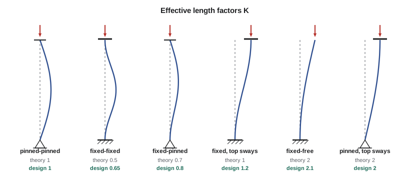
Real connections are never perfectly fixed, so design uses slightly larger factors than the theory. The most important distinction is between columns in braced frames, which cannot sway and have \(K \le 1.0\), and columns in moment frames free to sway, where \(K \ge 1.0\) and can be much larger. In braced frames it is normal and slightly conservative to take \(K = 1.0\). Sway frames are treated in lesson 11.
Why real columns fall below the Euler curve
If a column were perfectly straight, elastic up to yield and free of residual stress, its strength would be the smaller of the squash load \(AF_y\) and the Euler load. Real columns are weaker in the intermediate range for two reasons. First, every column has some initial crookedness, typically up to 1/1000 of its length, so it begins to bend as soon as load is applied and the bending adds stress. Second, residual stresses from rolling (lesson 2) mean that the flange tips, already in compression, yield early. The yielded parts no longer contribute to the bending stiffness, so the column buckles at a load below the Euler value computed with the full \(EI\).
Research in the 1960s and 1970s, coordinated by the Structural Stability Research Council (SSRC), computed and tested the strength of hundreds of real columns. The results fall in bands that depend on the shape, the steel and the manufacturing process, and the design curves in both North American standards are fitted to them.
The AISC column curve
AISC 360 gives the critical stress \(F_{cr}\) in terms of the ratio of yield stress to Euler stress:
The first expression covers inelastic buckling and the second elastic buckling. The factor 0.877 accounts for initial crookedness in the elastic range. The two meet at \(F_y/F_e = 2.25\), which for \(F_y = 50\) ksi is a slenderness \(KL/r = 113\). One curve covers all shapes in AISC; it was calibrated to give a reliable strength for columns with an initial crookedness of 1/1000.
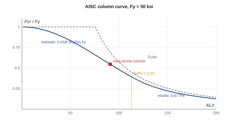
In the intermediate range, around the slenderness at which the Euler stress equals the yield stress, the design strength is about 60 percent of the yield load. This is where most building columns are, and where the effects of crookedness and residual stress are largest.
Local buckling and slender elements
The column curve assumes that the flanges and web do not buckle locally before the member as a whole. That is true when every element is nonslender: \(b_f/2t_f \le 0.56\sqrt{E/F_y}\) and \(h/t_w \le 1.49\sqrt{E/F_y}\), which are 13.5 and 35.9 for 50 ksi. Sections with slender elements are designed with an effective area under AISC 360 Section E7. Almost all rolled W shapes meet the limits; thin-walled HSS and built-up sections are the ones to watch.
Torsional and flexural-torsional buckling
Doubly symmetric W shapes and closed HSS almost always buckle by bending. Open sections with low torsional stiffness can instead twist, or bend and twist together. Single angles, tees, double angles and channels have their shear center away from the centroid, and their flexural-torsional buckling load can be lower than the flexural load about either axis. The standards give expressions for the elastic torsional and flexural-torsional buckling stresses, which are used in place of \(F_e\) in the column curve. Design tables for double angles and tees include these effects, which is one reason designers rely on them.
Sizing the mezzanine column
The interior mezzanine columns are 15 ft long, pinned at the base plate and at the girder connection above, and the mezzanine is braced, so \(K = 1.0\) about both axes. Each interior column supports a tributary area of 30 × 30 ft, and with its own weight the required strength is \(P_u = 900(1.2 \times 0.065 + 1.6 \times 0.125) + 1 = 251\) kips.
Worked problem
Interior mezzanine column
Check a W8x31 (\(A = 9.13\) in², \(r_x = 3.47\) in., \(r_y = 2.02\) in.) for \(P_u = 251\) kips with \(KL = 15\) ft about both axes, and select a section if it is not adequate.
Show solution
- Local buckling: \(b_f/2t_f = 9.20 < 13.5\) and \(h/t_w = 25.0 < 35.9\), so the section is nonslender for compression.
- Slenderness about the weak axis governs: \(KL/r_y = 180/2.02 = 89.1\).
- \[F_e = \frac{\pi^2(29{,}000)}{89.1^2} = 36.0\ \text{ksi} \qquad \frac{F_y}{F_e} = 1.39 < 2.25\]
- \[F_{cr} = 0.658^{1.39}(50) = 28.0\ \text{ksi} \qquad \phi_c P_n = 0.90(28.0)(9.13) = 230\ \text{kips} < 251\]
- Try W10x39 (\(A = 11.5\) in², \(r_y = 1.98\) in.): \(KL/r_y = 90.9\), \(F_e = 34.6\) ksi, \(F_{cr} = 27.3\) ksi.
- \[\phi_c P_n = 0.90(27.3)(11.5) = 283\ \text{kips} \ge 251\]
Answer: The W8x31 is about 8 percent short. The W10x39 gives \(\phi_c P_n = 283\) kips, a ratio of 0.89, and the W10x33 (233 kips) is also too small.
The program checks three candidate shapes, then asks what happens if the column is braced about its weak axis at mid-height, for example by a strut to the wall. It also checks one of the wall bracing angles in compression, which explains a decision made in lesson 11.
import math
# Mezzanine interior column: pinned at both ends, L = 15 ft, AISC 360 Chapter E
E, Fy = 29000.0, 50.0
trib = 30.0 * 30.0                        # ft2 of mezzanine
Pu = trib * (1.2 * 65 + 1.6 * 125) / 1000 + 1.2 * 0.035 * 15
print(f"Pu = {Pu:.0f} kips")

def phiPn(A, r, KL, Fy=Fy):
    slend = KL / r
    Fe = math.pi**2 * E / slend**2
    Fcr = 0.658**(Fy / Fe) * Fy if Fy / Fe <= 2.25 else 0.877 * Fe
    return 0.90 * Fcr * A, Fe, Fcr

shapes = {"W8x31": (9.13, 3.47, 2.02), "W10x33": (9.71, 4.19, 1.94), "W10x39": (11.5, 4.27, 1.98)}
KL = 15 * 12
for name, (A, rx, ry) in shapes.items():
    px, *_ = phiPn(A, rx, KL)
    py, Fe, Fcr = phiPn(A, ry, KL)
    gov = min(px, py)
    print(f"{name}: KL/rx = {KL/rx:5.1f}, KL/ry = {KL/ry:5.1f}, Fe = {Fe:5.1f} ksi, Fcr = {Fcr:5.1f} ksi, "
          f"phiPn = {gov:5.0f} kips  {'OK' if gov >= Pu else 'too small'}  ({Pu/gov:.2f})")

# Bracing the W8x31 about its weak axis at mid-height
A, rx, ry = shapes["W8x31"]
px, *_ = phiPn(A, rx, KL)
py, *_ = phiPn(A, ry, KL / 2)
print(f"W8x31 braced at mid-height: phiPn,x = {px:.0f} kips, phiPn,y = {py:.0f} kips")

# Single-angle brace L4x4x3/8 (A36) in compression, 12.5 ft to the crossing point, about the z axis
A_l, rz = 2.86, 0.779
p_l, Fe_l, Fcr_l = phiPn(A_l, rz, 12.5 * 12, Fy=36.0)
print(f"Angle brace: KL/r = {150/rz:.0f}, phiPn = {p_l:.1f} kips")Pu = 251 kips W8x31: KL/rx = 51.9, KL/ry = 89.1, Fe = 36.0 ksi, Fcr = 28.0 ksi, phiPn = 230 kips too small (1.09) W10x33: KL/rx = 43.0, KL/ry = 92.8, Fe = 33.2 ksi, Fcr = 26.6 ksi, phiPn = 233 kips too small (1.08) W10x39: KL/rx = 42.2, KL/ry = 90.9, Fe = 34.6 ksi, Fcr = 27.3 ksi, phiPn = 283 kips OK (0.89) W8x31 braced at mid-height: phiPn,x = 337 kips, phiPn,y = 355 kips Angle brace: KL/r = 193, phiPn = 17.4 kips
Two results deserve a comment. Bracing the column at mid-height about its weak axis more than halves its weak-axis slenderness, and the strong axis then governs at a much higher load. Columns in walls are often braced this way by girts. And a single angle brace with a length of 3.75 m to the crossing point has a slenderness near 190 about its weakest axis and can carry less than a tenth of its tensile strength in compression. That is why light X-bracing is designed to work in tension only.
Selecting columns efficiently
The AISC Manual has column tables (Table 4-1) that list \(\phi_c P_n\) for each shape at effective lengths in feet, using the weak-axis radius of gyration. To use them with different effective lengths about the two axes, compute \(KL_y\) and \((KL_x)/(r_x/r_y)\), and enter the table with the larger. The mezzanine design above is a single line of those tables.
Some guidance for choosing shapes:
- Nearly square W shapes in the column series (W200, W250, W310, W360 in metric; W8, W10, W12, W14 in US sizes) have large \(r_y\) and are efficient.
- HSS have equal radii of gyration about both axes and high torsional stiffness. They are efficient for lightly loaded columns and braces, and they make clean details.
- A heavier shape in the same series gains strength mainly through area, since \(r\) changes little.
- Column splices are usually placed about 1 m above a floor and every two or three stories, so one size runs through several floors.
Built-up members
Two angles back to back, or two channels with lacing or batten plates, act together only if they are connected often enough that each component cannot buckle on its own between connectors. The standards require the slenderness of each component between connectors to be a fraction of the slenderness of the whole member, and they modify the slenderness of the built-up member to account for shear deformation between connectors. For double-angle truss members this means stitch bolts or welds at a few points along each member.
Column bases and the load path
A column is only as good as its ends. At the base, the column bears on a steel base plate that spreads the load onto the concrete footing or pier, and anchor rods hold the column during erection and resist any uplift or shear. The plate is sized so that the bearing stress on the concrete stays within its design bearing strength, about \(0.65 \times 0.85f'_c\) on the loaded area, and thick enough that it does not bend excessively as a cantilever beyond the column flanges; AISC Design Guide 1 covers the procedure. For the mezzanine columns, a 12 × 12 in. plate about 1 in. thick on a grouted pier is typical. At the top, the girders frame into the column with simple connections, and the column cap or the connection angles must carry the reaction without crushing the column web. Erection matters too: until the deck and bracing are in place, the columns are free-standing on four anchor rods, as OSHA requires for steel erection, and the erector relies on those rods and on temporary guying for stability.
Common mistakes
MistakeUsing the strong-axis radius of gyration for a W shape with equal unbraced lengths.
InsteadBuckling occurs about the axis with the larger KL/r, usually the weak axis.
MistakeTaking K less than 1.0 for a column in a sway frame.
InsteadSway permitted means K is at least 1.0, often much more.
MistakeUsing the elastic expression \(0.877F_e\) when \(F_y/F_e\) is below 2.25.
InsteadUse \(0.658^{F_y/F_e}F_y\) in the inelastic range.
MistakeDesigning a slender angle brace to carry compression.
InsteadLong angle braces are nearly useless in compression; design X-bracing as tension-only.
Summary and key terms
- The Euler stress is \(\pi^2E/(KL/r)^2\); it depends on slenderness, not on yield strength.
- The effective length \(KL\) is the distance between inflection points of the buckled shape; \(K = 1.0\) for braced pinned columns.
- Initial crookedness and residual stresses lower the strength of intermediate columns below the Euler curve.
- AISC: \(F_{cr} = 0.658^{F_y/F_e}F_y\) for \(F_y/F_e \le 2.25\), else \(0.877F_e\); \(\phi_c = 0.90\).
- The mezzanine column, a W10x39 with \(KL = 15\) ft, has \(\phi_c P_n = 283\) kips against 251 kips.
- Euler load
- The elastic buckling load of a perfectly straight pinned column, π²EI/L².
- Slenderness ratio
- The effective length divided by the radius of gyration, KL/r.
- Radius of gyration
- r = √(I/A), a measure of how far the area lies from the axis.
- Effective length factor
- K, the ratio of the effective length to the actual length.
- Initial crookedness
- The out-of-straightness of a member before load, typically up to L/1000.
- Inelastic buckling
- Buckling after part of the cross-section has yielded.
- Flexural-torsional buckling
- Buckling by combined bending and twisting in open sections whose shear center and centroid do not coincide.
- Squash load
- The axial load that yields the whole cross-section, AFy.
Practice problems
Work each problem on paper first, then reveal the answer to check.
Find \(\phi_c P_n\) for a W10x39 with \(KL = 20\) ft about both axes.
Show answer
\(KL/r = 121\), \(F_e = 19.5\) ksi, \(F_y/F_e = 2.56 > 2.25\), so \(F_{cr} = 0.877(19.5) = 17.1\) ksi; \(\phi_c P_n = 0.9(17.1)(11.5) = 177\) kips.
A column is fixed at the base and pinned at the top in a braced frame. What K would you use?
Show answer
0.8, the recommended value for fixed-pinned ends, or 1.0 conservatively.
For what slenderness ratio does the Euler stress equal 50 ksi?
Show answer
\(KL/r = \pi\sqrt{29{,}000/50} = 75.7\).
Why are HSS efficient for lightly loaded columns?
Show answer
They have equal radii of gyration about both axes and high torsional stiffness, so they have no weak axis.
Lesson quiz · 5 questions
Score 60% or more to complete this lesson.
Create a free account to save your progress, take quizzes and earn a certificate.