
CIV-331 · Lesson 3 of 12 · 21 min
Tension members
Tension members are the simplest steel members to design, because tension straightens a member rather than buckling it. They are still worth careful study, because the connection at each end removes material and concentrates stress, and most tension members are governed by what happens at their ends. This lesson designs the bottom chord of the maintenance bay roof truss and introduces the three limit states of every tension member: yielding of the gross section, fracture of the net section and block shear.
Where tension members are used
Truss bottom chords and the diagonals of a Pratt truss under gravity load, hangers that carry a floor or a hoist from above, sag rods that support girts and purlins, and the diagonals of tension-only bracing are all tension members. Their cross-sections range from round bars and rods to angles, double angles, tees, channels, W shapes, HSS and plates. The choice usually depends on how the member is connected: a double angle or tee bolts or welds easily to a single gusset plate, and a W shape suits heavy truss chords with connections on both flanges.
Yielding of the gross section
Away from the connections, a tension member yields over its whole cross-section when the stress reaches \(F_y\). Yielding over a long length would stretch the member enough to distort the structure, so it is treated as a limit state:
Net area
At a bolted connection, the holes remove material and the stress across the remaining net section is higher than in the body of the member. Fracture across the net section is the second limit state. The net area is the gross area minus the area of the holes along the critical path:
Standard holes are 1/16 in. larger than the bolt, and AISC adds another 1/16 in. for damage around the hole when computing net area. For a 3/4 in. bolt the hole is 13/16 in. and the width deducted is 7/8 in.
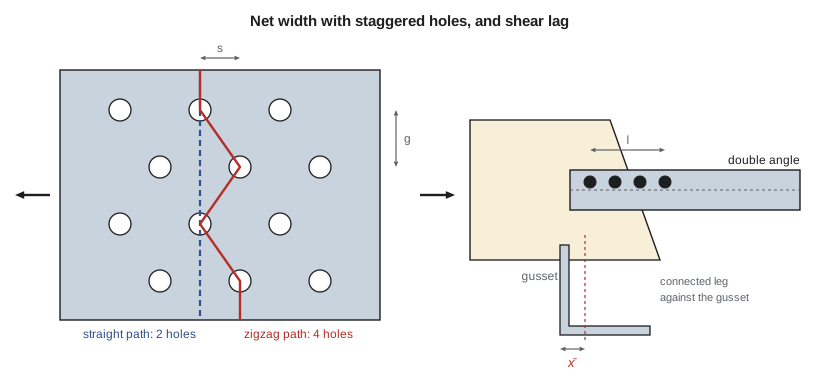
When holes are staggered, the fracture path can zigzag from hole to hole. A diagonal step is less weakening than a straight cut through the same number of holes, because part of the path is inclined. The empirical correction, proposed by Cochrane in 1922 and still used, adds \(s^2/4g\) for each diagonal link in the path:
where \(s\) is the stagger (the pitch between holes along the member) and \(g\) is the gauge (the transverse spacing between lines of holes). Every reasonable path is checked and the one with the smallest net width governs. For an angle, the gauge between holes in the two legs is measured along the centerline of the thickness: the sum of the two gauges from the heel minus the thickness.
Shear lag and the effective net area
When only part of a cross-section is connected, such as one leg of an angle, the force enters the member through the connected part and spreads into the unconnected part over some length. Near the connection the unconnected part carries less than its share, and the net section fails at a lower load than its full area would suggest. This is shear lag. The longer the connection and the closer the centroid of the member is to the plane of the connection, the smaller the loss.
AISC accounts for shear lag with the effective net area \(A_e = UA_n\). The general expression is \(U = 1 - \bar x/l\), where \(\bar x\) is the distance from the plane of the connection to the centroid of the connected part and \(l\) is the length of the connection, measured between the first and last bolts. For angles, AISC Table D3.1 also permits \(U = 0.80\) with four or more bolts in a line and \(0.60\) with three, and the larger value may be used. The rupture strength is
Because the net section uses \(F_u\) with a lower resistance factor, and the gross section uses \(F_y\) with a higher one, a member can be governed by either. For ductile behavior it is better if the gross section yields first, which needs a net-to-gross ratio of roughly \(F_y/F_u\) or more after the factors.
Block shear
A connection can also tear out as a block. The block separates along a shear plane parallel to the force, through the line of bolts, and a tension plane perpendicular to it. Block shear governs short connections with few bolts and thin material, and it must be checked in the member and in the gusset plate.
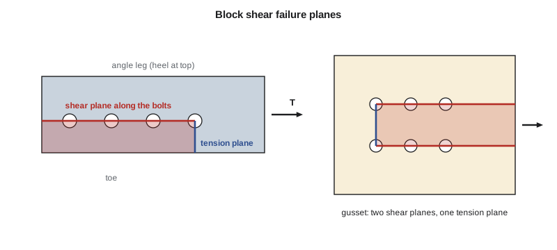
AISC combines fracture on the net tension area with the smaller of shear fracture on the net shear area and shear yielding on the gross shear area:
The factor \(U_{bs}\) is 1.0 when the tension stress is uniform, as in an angle or gusset with one line of bolts, and 0.5 when it is not, as in a coped beam with two lines of bolts.
Slenderness
Tension members do not buckle, but a very slender member sags under its own weight, vibrates and is easily damaged in handling. AISC recommends, without requiring, that \(L/r\) not exceed 300, except for rods and hangers.
Designing the bottom chord
The truss bottom chord L2L3 carries \(P_u = 132\) kips (lesson 1). Owen chooses a double angle, two L4x4x3/8 back to back with a 3/8 in. gap for the gusset plates. Each angle is connected to the gussets by one line of four 3/4 in. ASTM A325 bolts in standard holes, at 3 in. pitch with a 1.5 in. end distance, on a gage line 2.5 in. from the heel.
Worked problem
Bottom chord of the roof truss
Check two L4x4x3/8 (A36; each angle \(A = 2.86\) in², \(t = 0.375\) in., \(\bar x = 1.14\) in.) for \(P_u = 132\) kips, with one line of four 3/4 in. bolts per angle.
Show solution
- Tensile yielding:
- \[\phi_t P_n = 0.90(36)(5.72) = 185\ \text{kips}\]
- Tensile rupture. One hole per angle on the critical section, 7/8 in. wide:
- \[A_n = 2(2.86 - 0.875 \times 0.375) = 5.06\ \text{in}^2 \qquad U = 1 - \frac{1.14}{9.0} = 0.873 > 0.80\]
- \[\phi_t P_n = 0.75(58)(0.873)(5.06) = 192\ \text{kips}\]
- Block shear in each angle, with \(U_{bs} = 1.0\). The shear plane runs 1.5 + 3(3) = 10.5 in. along the bolt line, and the tension plane runs from the bolt line to the toe:
- \[A_{gv} = 10.5(0.375) = 3.94 \qquad A_{nv} = 3.94 - 3.5(0.875)(0.375) = 2.79 \qquad A_{nt} = (1.5 - 0.438)(0.375) = 0.398\ \text{in}^2\]
- \[R_n = \min[0.6(58)(2.79),\ 0.6(36)(3.94)] + 58(0.398) = 85.1 + 23.1 = 108.2\ \text{kips per angle}\]
- \[\phi R_n = 0.75(2)(108.2) = 162\ \text{kips}\]
- Slenderness in the plane of the truss: \(L/r = 120/1.23 = 98 < 300\).
Answer: Block shear governs: \(\phi R_n = 162\) kips against \(P_u = 132\) kips, a ratio of 0.81. The double angle is adequate.
Note that block shear governs here, and rupture is close behind. A longer connection, with a larger end distance or more bolts, raises both the block shear strength and \(U\); welding the angles to the gusset, as lesson 10 shows, avoids the hole deduction altogether.
Sofia's program makes the same checks and adds a staggered-hole example: a hanger plate for the hoist with four lines of holes, alternate lines staggered.
# Truss bottom chord L2L3: 2L4x4x3/8, A36, one line of four 3/4 in. bolts per angle
Fy, Fu = 36.0, 58.0
Tu = 132.0                       # kips, from lesson 1
A1, t, xbar = 2.86, 0.375, 1.14  # one angle: area (in2), thickness, centroid from back
leg, g = 4.0, 2.5                # leg length and gage from the heel (in.)
dh = 0.75 + 1/8                  # hole width for net area: 13/16 in. hole + 1/16 in.
n_bolts, pitch, end = 4, 3.0, 1.5

Ag = 2 * A1
yield_ = 0.90 * Fy * Ag
An = 2 * (A1 - dh * t)
l = (n_bolts - 1) * pitch
U = max(1 - xbar / l, 0.80 if n_bolts >= 4 else 0.60)
Ae = U * An
rupture = 0.75 * Fu * Ae
print(f"Tensile yielding: phiPn = 0.90 x {Fy:.0f} x {Ag:.2f} = {yield_:.1f} kips")
print(f"Tensile rupture:  An = {An:.3f} in2, U = {U:.3f}, Ae = {Ae:.3f} in2, phiPn = {rupture:.1f} kips")

# Block shear in each angle: shear along the bolt line, tension to the toe
Agv = (end + l) * t
Anv = Agv - (n_bolts - 0.5) * dh * t
Ant = (leg - g - dh / 2) * t
Rn = min(0.6 * Fu * Anv, 0.6 * Fy * Agv) + 1.0 * Fu * Ant
block = 2 * 0.75 * Rn
print(f"Block shear:      Agv = {Agv:.3f}, Anv = {Anv:.3f}, Ant = {Ant:.3f} in2, phiRn = {block:.1f} kips (two angles)")

phiPn = min(yield_, rupture, block)
print(f"Governing phiPn = {phiPn:.1f} kips, Pu = {Tu:.0f} kips, ratio = {Tu/phiPn:.2f}")
r = 1.23
print(f"Slenderness L/r = {120/r:.0f} (preferably 300 or less)")

# Staggered holes in a 10 x 1/2 in. hanger plate: gage 2.5 in., stagger 2 in.
b, tp, gs, s = 10.0, 0.5, 2.5, 2.0
paths = {"straight, 2 holes": b - 2 * dh,
         "zigzag, 4 holes": b - 4 * dh + 3 * s**2 / (4 * gs)}
for name, wn in paths.items():
    print(f"Plate path {name:18s}: net width = {wn:.3f} in.")
wn = min(min(paths.values()), 0.85 * b)
print(f"Critical net area = {wn*tp:.2f} in2")Tensile yielding: phiPn = 0.90 x 36 x 5.72 = 185.3 kips Tensile rupture: An = 5.064 in2, U = 0.873, Ae = 4.422 in2, phiPn = 192.4 kips Block shear: Agv = 3.938, Anv = 2.789, Ant = 0.398 in2, phiRn = 162.2 kips (two angles) Governing phiPn = 162.2 kips, Pu = 132 kips, ratio = 0.81 Slenderness L/r = 98 (preferably 300 or less) Plate path straight, 2 holes : net width = 8.250 in. Plate path zigzag, 4 holes : net width = 7.700 in. Critical net area = 3.85 in2
Worked problem
Hanger plate with staggered holes
A 10 × 1/2 in. hanger plate has four lines of 3/4 in. bolt holes at a 2.5 in. gage, with alternate lines staggered 2 in. Find the critical net area.
Show solution
- Straight path through two holes in one cross-section:
- \[w_n = 10 - 2(0.875) = 8.25\ \text{in.}\]
- Zigzag path through all four holes, with three diagonal links:
- \[w_n = 10 - 4(0.875) + 3\,\frac{2^2}{4(2.5)} = 10 - 3.50 + 1.20 = 7.70\ \text{in.}\]
Answer: The zigzag path governs: \(A_n = 7.70(0.5) = 3.85\) in², which is below the limit of \(0.85A_g = 4.25\) in² for connecting plates.
Rods, cables and pin-connected members
Threaded rods are used for hangers, sag rods and light bracing. AISC treats them like bolts in tension, with a nominal stress of \(0.75F_u\) on the gross area of the rod. Cables and strands have their own standards. Pin-connected plates and eyebars, once common in bridges, appear today in exposed structures; AISC limits their proportions so that the plate does not fracture or dish around the pin.
Practical points
- Size tension members by the connection, not by the body. Start from the bolt or weld pattern and check net fracture and block shear first.
- Keep gussets compact and connections concentric. Eccentric connections add bending that the simple checks do not cover.
- For double angles, add stitch bolts or fillers at intervals so the two angles act together and do not rattle.
- A truss chord also carries load reversal in some combinations: under wind uplift the bottom chord may go into compression and need bracing to the roof.
Common mistakes
MistakeUsing the gross area for fracture.
InsteadFracture uses the effective net area, reduced for holes and shear lag.
MistakeDeducting only the bolt diameter for each hole.
InsteadDeduct the bolt diameter plus 1/8 in. in total.
MistakeChecking only the straight path when holes are staggered.
InsteadCheck every plausible zigzag path and add \(s^2/4g\) for each diagonal link.
MistakeForgetting block shear because the member area is large.
InsteadBlock shear depends on the connection geometry and often governs short connections.
Summary and key terms
- Tensile yielding: \(\phi P_n = 0.90F_y A_g\).
- Tensile rupture: \(\phi P_n = 0.75F_u A_e\) with \(A_e = UA_n\) and \(U = 1 - \bar x/l\).
- Staggered holes: \(w_n = w - \sum d_h + \sum s^2/4g\); the path with the smallest net width governs.
- Block shear combines tension rupture with the smaller of shear rupture and shear yielding, with \(U_{bs}\) of 1.0 or 0.5.
- The bottom chord, two L4x4x3/8, has \(\phi P_n = 162\) kips against 132 kips, governed by block shear.
- Gross area
- The full cross-sectional area of a member.
- Net area
- The area remaining after deducting the holes along a fracture path.
- Shear lag
- The uneven stress in a member near a connection that engages only part of the cross-section.
- Effective net area
- Ae = U An, the net area reduced for shear lag.
- Stagger
- The longitudinal spacing between holes in adjacent lines.
- Gauge
- The transverse spacing between lines of holes.
- Block shear
- Tearing out of a block of material along combined shear and tension planes at a connection.
- Hole allowance
- The width deducted for each hole in computing net area.
Practice problems
Work each problem on paper first, then reveal the answer to check.
A single L4x4x3/8 brace is connected by one leg with three 3/4 in. bolts at 3 in. Find \(\phi P_n\) for rupture with \(U\) from Table D3.1.
Show answer
\(A_n = 2.86 - 0.328 = 2.53\) in²; \(U = 0.60\); \(\phi P_n = 0.75(58)(0.60)(2.53) = 66.1\) kips (\(1 - 1.14/6 = 0.81\) would give 89.2 kips, and the larger may be used).
Why does a punched hole get a larger deduction than a drilled hole?
Show answer
Punching damages and work-hardens a ring of material around the hole, which may crack.
Find the design strength of a 1 in. diameter A36 threaded rod hanger.
Show answer
\(\phi R_n = 0.75(0.75)(58)(0.785) = 25.6\) kips.
What happens to block shear strength if the end distance is increased?
Show answer
The shear plane lengthens, so block shear strength rises.
Lesson quiz · 5 questions
Score 60% or more to complete this lesson.
Create a free account to save your progress, take quizzes and earn a certificate.