
CIV-330 · Lesson 5 of 12 · 21 min
Serviceability: deflection and crack control
A beam can be perfectly safe and still be a failure. If a floor sags enough to crack the partitions it carries, or if its cracks are wide enough to stain the soffit and let water reach the bars, the owner will rightly complain. Serviceability limit states are checked under specified loads, not factored loads, and they often govern the depth of floors in long spans. This lesson covers the two main checks: deflection and crack control.
Two ways to control deflection
ACI 318 offers two routes. The simple route is to make the member at least as thick as a span-based minimum, in which case deflections need not be calculated, provided the member does not support or attach to partitions or other elements likely to be damaged by large deflections. The second route is to calculate the deflections and compare them with permissible limits.
| Member | Simply supported | One end continuous | Both ends continuous | Cantilever |
|---|---|---|---|---|
| Beams and ribbed one-way slabs | l/16 | l/18.5 | l/21 | l/8 |
| Solid one-way slabs | l/20 | l/24 | l/28 | l/10 |
For the office beam, simply supported over a span of 25 ft, the minimum depth would be \(300/16 = 18.8\) in. The 24 in. beam passes easily. However, the beam supports gypsum partitions, so the table does not apply strictly and Owen checks the deflection by calculation.
| Type of member | Deflection considered | Limit |
|---|---|---|
| Flat roofs not supporting elements likely to be damaged | Immediate, due to live (or snow) load | l/180 |
| Floors not supporting elements likely to be damaged | Immediate, due to live load | l/360 |
| Roofs or floors supporting elements likely to be damaged | Long-term part after attachment plus immediate live load | l/480 |
| Roofs or floors supporting elements not likely to be damaged | Long-term part after attachment plus immediate live load | l/240 |
Cracked section properties
Deflection calculations need the stiffness of the member, and that depends on how badly it is cracked. Before cracking, the gross moment of inertia \(I_g\) applies. After cracking, at a section where the moment exceeds \(M_{cr}\), the concrete below the neutral axis is ignored and the steel is transformed into an equivalent area \(nA_s\) of concrete. The neutral axis depth \(kd\) of the cracked transformed section comes from equating first moments of area about the axis:
and the cracked moment of inertia is
For a typical beam \(I_{cr}\) is 30 to 50 percent of \(I_g\). A real beam is cracked only where the moment exceeds \(M_{cr}\); between cracks the concrete still carries some tension (tension stiffening), so the effective stiffness lies between the cracked and gross values.
Effective moment of inertia
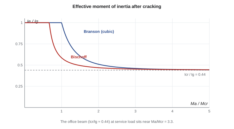
ACI 318-19 replaced the long-used Branson equation with an expression derived by Bischoff, which models tension stiffening more realistically for lightly reinforced members:
Here \(M_a\) is the maximum service moment in the span at the stage being considered. The factor 2/3 on \(M_{cr}\) accounts for restraint shrinkage, which cracks members at lower loads than the modulus of rupture predicts. For lightly reinforced members, especially slabs, the Bischoff form gives noticeably larger deflections than Branson did; for beams with 1 percent steel or more the two are close.
Immediate and long-term deflection
With \(I_e\) known, immediate deflections follow from elastic beam formulas. For a simply supported beam under uniform load the midspan deflection is \(5wL^4/(384E_cI_e)\). Because \(I_e\) depends on the moment, the dead load deflection and the deflection under dead plus live load must be computed separately with their own \(I_e\); the live load deflection is the difference. Superposing a live load deflection computed with \(I_e\) at the full load on a dead load deflection with its own \(I_e\) is the correct way to account for the nonlinearity.
Under sustained load, creep and shrinkage increase the deflection. ACI 318 multiplies the immediate deflection due to sustained load by
where \(\rho' = A'_s/bd\) is the compression steel ratio at midspan, and \(\xi\) is a time-dependent factor: 1.0 at 3 months, 1.2 at 6 months, 1.4 at 12 months and 2.0 at 5 years or more. The sustained load is the dead load plus any live load that is present for long periods, such as storage.
The deflection compared with the l/480 or l/240 limit is the part that occurs after the partitions are attached: the long-term creep deflection under sustained load plus the immediate deflection due to live load. Some designers subtract the part of the dead load deflection that occurs before partitions are built; others conservatively include it all, as below.
Worked problem
Deflection of the office floor beam
Check the office beam (14 × 24 in., \(d = 21.5\) in., 4 #8, \(f'_c = 4{,}000\) psi, simply supported span 25 ft) under service loads \(D = 1.40\) kip/ft and \(L = 0.80\) kip/ft. It supports partitions likely to be damaged.
Show solution
- Properties: \(E_c = 3{,}605{,}000\) psi, \(n = 8.04\), \(f_r = 474\) psi.
- \[I_g = \frac{14(24)^3}{12} = 16{,}128\ \text{in}^4 \qquad M_{cr} = \frac{474(16{,}128)}{12} = 637{,}000\ \text{lb·in.} = 53.1\ \text{kip·ft}\]
- Cracked section: \(7(kd)^2 = 25.4(21.5 - kd)\) gives \(kd = 7.20\) in. and
- \[I_{cr} = \frac{14(7.20)^3}{3} + 25.4(21.5 - 7.20)^2 = 6940\ \text{in}^4\]
- Service moments: \(M_D = 1.40(25)^2/8 = 109\) kip·ft and \(M_{D+L} = 172\) kip·ft. Bischoff:
- \[I_{e,D} = \frac{6940}{1 - \Big(\frac{35.4}{109}\Big)^2(1 - 0.430)} = 7381\ \text{in}^4 \qquad I_{e,D+L} = 7112\ \text{in}^4\]
- Immediate deflections:
- \[\Delta_D = \frac{5(116.7)(300)^4}{384(3{,}605{,}000)(7381)} = 0.46\ \text{in.} \qquad \Delta_{D+L} = 0.75\ \text{in.} \qquad \Delta_L = 0.29\ \text{in.}\]
- Live load check: \(0.29 \le 300/360 = 0.83\) in. Long-term with \(\lambda_\Delta = 2.0\) (no compression steel):
- \[\Delta = 2.0(0.46) + 0.29 = 1.22\ \text{in.} > \frac{300}{480} = 0.63\ \text{in.}\]
Answer: The live load deflection is fine, but the long-term deflection fails the l/480 limit for partitions on a simple span. It would just pass the l/240 limit of 1.25 in.
The result is not a reason to redesign yet. The simple span model is very conservative for this beam, which is continuous with the columns at one end and with the next span at the other. In CIV-321 the corridor frame analysis gave end moments that reduce the midspan moment substantially; a fixed-pinned beam deflects only about 40 percent as much as a simply supported one. With the continuous moments and a weighted average \(I_e\), the long-term plus live deflection drops to about 0.5 in., inside the 0.63 in. limit. Owen records both calculations, and the team adds 2 #5 compression bars at midspan as cheap insurance, which reduces \(\lambda_\Delta\) to about 1.8.
import math
# Office floor beam serviceability, ACI 318: Bischoff effective moment of inertia
fc, fy, Es = 4000.0, 60000.0, 29e6
b, h, d, As = 14.0, 24.0, 21.5, 3.16           # 4 #8
L = 25 * 12.0
wD, wL = 1400 / 12, 800 / 12                    # service loads, lb/in.
Ec = 57000 * math.sqrt(fc); n = Es / Ec
fr = 7.5 * math.sqrt(fc)
Ig = b * h**3 / 12; yt = h / 2
Mcr = fr * Ig / yt
kd = (-n * As + math.sqrt((n * As) ** 2 + 2 * b * n * As * d)) / b
Icr = b * kd**3 / 3 + n * As * (d - kd) ** 2
print(f"n = {n:.2f}, Mcr = {Mcr/12000:.1f} kip-ft, kd = {kd:.2f} in.")
print(f"Ig = {Ig:.0f} in4, Icr = {Icr:.0f} in4")

def Ie(Ma):
    Mc = 2 / 3 * Mcr                            # Bischoff form with (2/3)Mcr
    if Ma <= Mc: return Ig
    return Icr / (1 - (Mc / Ma) ** 2 * (1 - Icr / Ig))

def defl(w, I):
    return 5 * w * L**4 / (384 * Ec * I)

MD = wD * L**2 / 8; MDL = (wD + wL) * L**2 / 8
dD = defl(wD, Ie(MD)); dDL = defl(wD + wL, Ie(MDL))
dL = dDL - dD
lam = 2.0 / (1 + 50 * 0.0)                     # xi = 2.0 for 5 years or more, no compression steel
dlong = lam * dD + dL
print(f"Ie(D) = {Ie(MD):.0f}, Ie(D+L) = {Ie(MDL):.0f} in4")
print(f"immediate: dead {dD:.2f} in., dead+live {dDL:.2f} in., live {dL:.2f} in.")
print(f"live limit L/360 = {L/360:.2f} in. -> {'OK' if dL <= L/360 else 'exceeds'}")
print(f"long-term + live = {dlong:.2f} in., limit L/480 = {L/480:.2f} in. -> {'OK' if dlong <= L/480 else 'exceeds'}")

# Crack control by bar spacing
fs = 2 / 3 * fy
cc = 1.5 + 0.375                                # clear cover to the #8 bars (outside #3 stirrups)
smax = min(15 * (40000 / fs) - 2.5 * cc, 12 * (40000 / fs))
s = (b - 2 * (cc + 0.5)) / 3
print(f"crack control: s max = {smax:.1f} in., actual bar spacing = {s:.2f} in.")n = 8.04, Mcr = 53.1 kip-ft, kd = 7.20 in. Ig = 16128 in4, Icr = 6940 in4 Ie(D) = 7381, Ie(D+L) = 7112 in4 immediate: dead 0.46 in., dead+live 0.75 in., live 0.29 in. live limit L/360 = 0.83 in. -> OK long-term + live = 1.22 in., limit L/480 = 0.62 in. -> exceeds crack control: s max = 10.3 in., actual bar spacing = 3.08 in.
Why cracks need control
Flexural cracks in reinforced concrete are inevitable, because the steel cannot work until the concrete around it has cracked. What matters is their width. Narrow, well-distributed cracks are invisible to the casual eye and close up when load is removed; a few wide cracks look alarming, let water and chlorides reach the steel, and in parking structures accelerate corrosion. Crack width grows with the steel stress and with the distance from the bar to the concrete surface, and it falls when the same steel area is provided as more, smaller bars at closer spacing.
ACI 318 controls cracking by limiting the spacing of bars closest to the tension face, a rule based on the work of Frosch:
where \(f_s\) is the steel stress at service load in psi (which may be taken as \(\tfrac{2}{3}f_y\)), \(c_c\) is the least distance from the bar surface to the tension face, and \(s\) is the center-to-center spacing in inches. The rule does not specify a crack width; it reflects the idea that for normal cover, crack width is controlled by bar spacing. For members exposed to aggressive environments, designers use smaller spacing and additional protection such as sealers.
Worked problem
Crack control for the office beam
Check the spacing of the 4 #8 bars of the office beam, 1.5 in. cover to #3 stirrups, interior exposure.
Show solution
- \[f_s = \tfrac{2}{3}(60{,}000) = 40{,}000\ \text{psi} \qquad c_c = 1.5 + 0.375 = 1.875\ \text{in.}\]
- \[s_{max} = 15(1.0) - 2.5(1.875) = 10.3\ \text{in.} \le 12(1.0)\]
- Actual spacing between bar centers: \((14 - 2(1.875 + 0.5))/3 = 3.08\) in.
Answer: 3.08 in. is far below the 10.3 in. limit.
Two further rules complete crack control. Deep beams, deeper than 36 in., need skin reinforcement on the side faces near the tension zone, because wide cracks can form in the web between the main bars and the neutral axis. And the parking level of the garage, exposed to de-icing chemicals, is detailed with closer bar spacing and protected by a sealer or membrane as ACI 362 recommends.
Other serviceability concerns
- Vibration. Long, light floors can bounce under footfall. Concrete floors are heavy and rarely a problem in offices, but floors with spans over about 10 m or with rhythmic activities deserve a frequency check.
- Shrinkage cracking in slabs. Restraint by walls and columns causes cracks unrelated to load; control joints, pour strips and shrinkage reinforcement manage them.
- Camber and construction loads. Shoring removal and early loading at low concrete strength increase long-term deflection; specifying a minimum strength before stripping helps.
- Durability. Cover, concrete quality and crack control together govern the service life of exposed concrete.
Common mistakes
MistakeComputing service-load deflection with factored loads.
InsteadServiceability checks use specified (service) loads.
MistakeUsing one \(I_e\) for dead and live load deflections.
InsteadCompute \(I_e\) at each load level; find live load deflection as the difference.
MistakeApplying the long-term multiplier to the live load deflection.
InsteadOnly sustained loads creep; transient live load gets no multiplier.
MistakeUsing a few large bars to save placing labor in a crack-sensitive member.
InsteadMore, smaller bars at closer spacing give narrower cracks for the same area.
Summary and key terms
- Deflection is controlled by minimum thickness tables or by calculation compared with limits from l/180 to l/480.
- Cracked section analysis uses the transformed steel area \(nA_s\) and ignores concrete in tension.
- ACI 318-19 uses the Bischoff expression for \(I_e\), with \((2/3)M_{cr}\) to reflect restraint shrinkage.
- Long-term deflection multiplies the sustained-load deflection by a factor of up to 2.0, reduced by compression steel.
- Crack control limits bar spacing to \(15(40{,}000/f_s) - 2.5c_c\), at most \(12(40{,}000/f_s)\).
- The office beam passes the live load limit but needs the continuous-span analysis to pass the l/480 limit.
- Serviceability
- The performance of a structure under normal use, including deflection, cracking and vibration.
- Effective moment of inertia
- An average stiffness between gross and cracked values that accounts for partial cracking.
- Cracked transformed section
- A section in which concrete in tension is ignored and steel is replaced by n times its area of concrete.
- Tension stiffening
- The contribution of uncracked concrete between cracks to member stiffness.
- Long-term deflection multiplier
- The factor applied to immediate sustained-load deflection to account for creep and shrinkage.
- Skin reinforcement
- Longitudinal bars on the side faces of deep beams that limit web cracks.
- Bar spacing limit
- The maximum spacing of tension bars set by ACI 318 to control crack width.
- Restraint shrinkage
- Tensile stress caused when drying shrinkage is prevented by supports or reinforcement.
Practice problems
Work each problem on paper first, then reveal the answer to check.
What minimum thickness avoids deflection calculation for a one-way slab with both ends continuous and a 14 ft span?
Show answer
\(168/28 = 6.0\) in.
A beam has an immediate dead load deflection of 8 mm (0.32 in.) and no compression steel. What is the creep part after five years?
Show answer
\(2.0 \times 8 = 16\) mm (0.64 in.) additional; total sustained deflection 24 mm (0.96 in.).
Why is live load deflection found as a difference rather than computed directly?
Show answer
\(I_e\) depends on the total moment; the live load acts on an already cracked beam.
Compute the spacing limit for \(f_s = 36{,}000\) psi and \(c_c = 2.0\) in.
Show answer
\(15(1.111) - 5.0 = 11.7\) in., but not more than \(12(1.111) = 13.3\) in.; limit 11.7 in.
How does adding compression steel reduce long-term deflection?
Show answer
It restrains creep of the compression zone, lowering the multiplier \(s/(1+50\rho')\) or \(\xi/(1+50\rho')\).
Lesson quiz · 5 questions
Score 60% or more to complete this lesson.
Create a free account to save your progress, take quizzes and earn a certificate.