
CIV-330 · Lesson 11 of 12 · 20 min
Slender columns and column detailing
A tall, thin column bends sideways under load. The axial load then acts on a deflected shape, adding a second-order moment equal to the load times the lateral deflection, and the column can fail at a load well below the capacity of its cross-section. This lesson explains when slenderness matters, how the moment magnifier method accounts for it in braced and sway frames, and how columns are detailed with ties and spirals so that they can reach their calculated strength. The example is a tall interior column of the fleet garage.
Slenderness and second-order effects
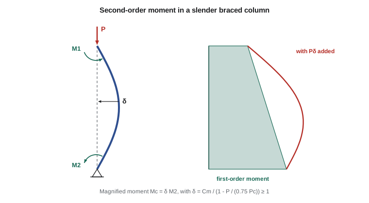
A column's slenderness is measured by the ratio \(kl_u/r\): the effective length divided by the radius of gyration. The unsupported length \(l_u\) is the clear distance between floors, beams or other members that brace the column. The effective length factor \(k\) converts the real end conditions into the length of an equivalent pin-ended column; it is between 0.5 and 1.0 for columns in frames braced against sway and greater than 1.0 for columns in sway frames. For rectangular columns \(r\) may be taken as \(0.3h\) in the direction of bending, and for circular columns \(0.25\) times the diameter.
There are two distinct second-order effects. In a braced frame, the column deflects between its ends, adding a moment that is largest near mid-height: the \(P\delta\) effect. In a sway frame, the whole story translates laterally by \(\Delta\), and the gravity load on all the columns acting through that translation adds moment at the column ends: the \(P\Delta\) effect. The two are treated separately, because the first depends on the individual column and the second on the whole story.
Braced or sway?
A story is considered nonsway when the lateral load resisting elements, such as shear walls and braced frames, are stiff enough that second-order effects from story drift are small. ACI 318 measures this with the stability index
where \(\sum P\) is the total factored vertical load in the story, \(\Delta_o\) is the first-order relative lateral deflection of the top and bottom of the story under the story shear \(V\), and \(l_c\) is the story height. If \(Q\) is 0.05 or less, sway effects add no more than about 5 percent to the column moments and the story may be treated as braced.
The garage has concrete shear walls around the wash bay and the stair, which brace the interior columns of the parking structure. Owen computes \(Q = 0.02\) from the frame model, so the interior columns are designed as braced. The office building, braced by its stair and elevator cores, is also non-sway.
When can slenderness be ignored?
For columns in nonsway frames, ACI 318 allows slenderness effects to be neglected when
where \(M_1\) and \(M_2\) are the smaller and larger end moments, and \(M_1/M_2\) is negative for single curvature and positive for double curvature (the sign convention changed in recent editions; check it carefully). Columns in sway frames need slenderness effects considered when \(kl_u/r\) exceeds 22. Unlike the Canadian limit, the ACI limit does not depend on the axial load level.
Most columns in braced building frames fall below the limit and are designed as short columns. Tall columns in garages, warehouses, atria and industrial buildings often exceed it.
The moment magnifier method for braced columns
Elastic stability theory shows that an axial load \(P\) amplifies the first-order moments in a pin-ended member by approximately \(1/(1 - P/P_c)\), where \(P_c\) is the Euler buckling load. The codes use this result with adjustments for the shape of the moment diagram and for the uncertainty in stiffness:
The factor \(C_m = 0.6 - 0.4M_1/M_2\) (with the sign convention above) converts an unequal end moment diagram into an equivalent uniform moment; for single curvature with equal end moments it is 1.0, and for reverse curvature it can be as low as 0.2. When there are transverse loads between the ends of the column, \(C_m = 1.0\).
The flexural stiffness \(EI\) must account for cracking and for creep under sustained load, both of which make the column more flexible and the magnification larger. The codes give two expressions:
where \(\beta_{dns}\) is the ratio of the factored sustained axial load to the total factored axial load. The first form is more accurate for heavily reinforced columns; the second is simpler and conservative for lightly reinforced ones. A third expression uses the member's actual reinforcement and axial load level.
Finally, the design moment may not be less than \(P_u(0.6 + 0.03h)\) with \(h\) in inches, which represents the accidental eccentricity in a slender column. If the column is too slender, with \(kl_u/r > 100\), a full second-order analysis is required instead of the magnifier.
Worked problem
Tall garage column
An interior garage column is 16 × 16 in. with 8 #7 bars (three per face) and \(f'_c = 5{,}000\) psi. Its unsupported height is 20 ft from the slab on grade to the underside of the parking level beams, braced at both ends (\(k = 1.0\) conservatively). Factored loads: \(P_u = 250\) kips, end moments 22.5 and 45 kip·ft in single curvature, \(\beta_{dns} = 0.6\). Check slenderness and find the design moment.
Show solution
- \[r = 0.3(16) = 4.8\ \text{in.} \qquad \frac{kl_u}{r} = \frac{240}{4.8} = 50\]
- With single curvature \(M_1/M_2 = -0.5\): \(\text{limit} = 34 + 12(-0.5) = 28 < 50 \to\) slender.
- \[(EI)_{eff} = \frac{0.4(4{,}031{,}000)(5461)}{1.6} = 5.50 \times 10^9\ \text{lb·in}^2 \qquad P_c = \frac{\pi^2(5.50 \times 10^9)}{240^2} = 943\ \text{kips}\]
- \[C_m = 0.6 - 0.4(-0.5) = 0.80 \qquad \delta = \frac{0.80}{1 - \dfrac{250}{0.75(943)}} = 1.24\]
- Minimum moment: \(250(0.6 + 0.48)/12 = 22.5\) kip·ft, less than \(M_2\).
- \[M_c = 1.24(45) = 55.7\ \text{kip·ft}\]
- From the interaction diagram of the section (computed below), at \(P_u = 250\) kips the column provides \(\phi M_n = 182\) kip·ft.
Answer: The column is slender and the moment is magnified by 24 percent to 55.7 kip·ft, but the section is still adequate with a large margin.
import math
# Slender nonsway column by moment magnification, ACI 318
fc, fy, Es = 5000.0, 60000.0, 29e6
b = h = 16.0
lu, k = 20 * 12.0, 1.0
Pu, M1, M2 = 250.0, -22.5, 45.0           # kips, kip-ft; M1 negative = single curvature
beta_dns = 0.6
Ec = 57000 * math.sqrt(fc); Ig = b * h**3 / 12
r = 0.3 * h
slender = k * lu / r
limit = min(34 + 12 * M1 / M2, 40)
print(f"klu/r = {slender:.1f}, limit = {limit:.1f} -> {'slender' if slender > limit else 'short'}")
EI = 0.4 * Ec * Ig / (1 + beta_dns)
Pc = math.pi**2 * EI / (k * lu) ** 2 / 1000
Cm = 0.6 - 0.4 * M1 / M2
delta = max(Cm / (1 - Pu / (0.75 * Pc)), 1.0)
M2min = Pu * (0.6 + 0.03 * h) / 12
Mc = delta * max(M2, M2min)
print(f"EI = {EI:.3e} lb-in2, Pc = {Pc:.0f} kips, Cm = {Cm:.2f}, delta = {delta:.3f}")
print(f"minimum moment = {M2min:.1f} kip-ft, magnified design moment Mc = {Mc:.1f} kip-ft")

# Section check: 8 #7 (3 per face), lesson 10 routine
ecu = 0.003; b1 = 0.80
layers = [(1.80, 2.5), (1.20, 8.0), (1.80, 13.5)]
def point(c):
    a = min(b1 * c, h); Cc = 0.85 * fc * a * b
    P = Cc; M = Cc * (h / 2 - a / 2)
    for As, y in layers:
        fs = max(-fy, min(fy, Es * ecu * (c - y) / c))
        f = As * fs - (0.85 * fc * As if y < a else 0)
        P += f; M += f * (h / 2 - y)
    et = ecu * (13.5 - c) / c; ety = fy / Es
    phi = 0.90 if et >= ety + 0.003 else (0.65 if et <= ety else 0.65 + 0.25 * (et - ety) / 0.003)
    return phi * P / 1000, phi * M / 12000
lo, hi = 2.0, 60.0
for _ in range(60):
    c = (lo + hi) / 2
    lo, hi = (c, hi) if point(c)[0] < Pu else (lo, c)
P, Mn = point(c)
print(f"at Pu = {Pu:.0f} kips: c = {c:.2f} in., phiMn = {Mn:.0f} kip-ft vs Mc = {Mc:.0f} -> {'OK' if Mc <= Mn else 'not OK'}")
print(f"magnification adds {Mc - M2:.0f} kip-ft ({(Mc/M2 - 1)*100:.0f}%) to the first-order moment")klu/r = 50.0, limit = 28.0 -> slender EI = 5.503e+09 lb-in2, Pc = 943 kips, Cm = 0.80, delta = 1.237 minimum moment = 22.5 kip-ft, magnified design moment Mc = 55.7 kip-ft at Pu = 250 kips: c = 7.03 in., phiMn = 182 kip-ft vs Mc = 56 -> OK magnification adds 11 kip-ft (24%) to the first-order moment
Two things stand out. First, the ACI limit for this single-curvature column is only 28, much stricter than the Canadian limit for the same column, because the US expression does not account for the moderate axial load. Second, the magnifier grows quickly as \(P_u\) approaches \(0.75P_c\); at 400 kips this column would have \(\delta\) near 2, a sign that a larger section is needed. Priya keeps the 16 in. column but asks Owen to confirm \(k\) from the stiffness of the beams, which will probably reduce it below 1.0.
Sway frames
In a sway frame the end moments from lateral loads are amplified by the story-wide \(P\Delta\) effect. ACI 318 gives three ways to find the sway moments: a second-order elastic analysis, the stability index method, in which the sway moments are multiplied by \(1/(1 - Q)\), and a sway magnifier \(\delta_s = 1/(1 - \sum P_u/(0.75\sum P_c))\) based on all the columns of the story. The magnified sway moments are added to the nonsway moments from gravity loads. Each column must still be checked for the \(P\delta\) effect along its length.
Modern practice increasingly uses second-order analysis software directly, with member stiffnesses reduced for cracking (0.35\(I_g\) for beams and 0.70\(I_g\) for columns is typical) and further reduced in strength checks. The magnifier methods remain valuable as checks and for understanding.
Column ties
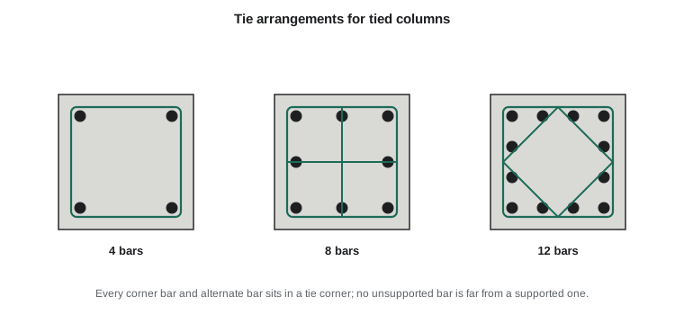
Ties hold the longitudinal bars in position during construction, prevent the bars from buckling outward when the concrete is highly compressed, provide some confinement, and act as shear reinforcement. Their rules are prescriptive:
- Tie size: at least #3 for longitudinal bars #10 and smaller, and #4 for #11 and larger and for bundles.
- Tie spacing: not more than the least of 16 longitudinal bar diameters, 48 tie diameters, and the least column dimension. For the garage column with #7 bars and #3 ties: \(16 \times 0.875 = 14\) in., \(48 \times 0.375 = 18\) in., 16 in., so ties at 14 in.
- Every corner bar and alternate bar must be supported by the corner of a tie with an included angle of not more than 135 degrees, and no bar may be more than 150 mm (6 in.) clear from a supported bar.
- Ties start and stop within half a tie spacing of the slab or beam above and below, and are closer near splices and in beam-column joints where required.
Spirals are designed so that the confined core, after the cover spalls, can carry at least the load the column carried before spalling. The required volumetric ratio is
with clear spacing between turns typically 25 to 75 mm (1 to 3 in.).
Splices and joints
Column bars are usually lap-spliced just above each floor. Where the column size reduces, the lower bars are offset-bent with a slope of no more than 1 in 6 to fit inside the upper column, and extra ties resist the outward thrust at the bends. Where bars are always in compression, end-bearing splices or compression laps are permitted, but columns that see tension under wind or seismic load need tension lap splices or mechanical couplers.
Beam-column joints are where beams and columns meet, and they are among the most congested parts of a concrete frame. Column ties continue through the joint unless beams on all four sides confine it. In seismic regions, joints are designed for shear explicitly and are given closely spaced hoops, and the design philosophy of strong columns and weak beams requires columns to be stronger in flexure than the beams framing into them.
Common mistakes
MistakeUsing the column's full height instead of the clear height.
Instead\(l_u\) is the clear distance between members that brace the column.
MistakeApplying the braced-frame slenderness limit to a sway frame.
InsteadCheck the stability index first; sway frames have stricter limits and need \(P\Delta\) moments.
MistakeUsing a positive \(M_1/M_2\) for single curvature in current ACI 318.
InsteadCurrent ACI 318 uses a negative ratio for single curvature and \(C_m = 0.6 - 0.4M_1/M_2\).
MistakeSpacing ties at the column dimension when the bars are small.
InsteadThe 16-bar-diameter limit often governs with small longitudinal bars.
Summary and key terms
- Slender columns lose strength because the axial load acts on the lateral deflection (\(P\delta\) in braced, \(P\Delta\) in sway frames).
- A story is braced if the stability index \(Q \le 0.05\).
- ACI 318 neglects slenderness in nonsway columns when \(kl_u/r \le 34 + 12M_1/M_2 \le 40\).
- The magnified moment is \(C_m M_2/(1 - P/(0.75P_c))\), with \(EI\) reduced for cracking and creep, and not less than the minimum moment.
- The 20 ft garage column is slender: \(\delta = 1.24\) and \(M_c = 55.7\) kip·ft, within its 182 kip·ft capacity.
- Ties at no more than 16\(d_b\), 48 tie diameters or the least dimension hold bars against buckling; spirals confine the core.
- Slenderness ratio
- The effective length divided by the radius of gyration, klu/r.
- Effective length factor
- The factor k that converts actual end restraint to an equivalent pin-ended length.
- Unsupported length
- The clear distance between members that brace a column.
- Stability index
- The ratio Q of second-order to first-order story moment, used to classify sway.
- Moment magnifier
- The factor by which first-order moments are increased to account for second-order effects.
- Equivalent moment factor
- Cm, which converts unequal end moments into an equivalent uniform moment.
- Critical buckling load
- The Euler load Pc = π²EI/(klu)², with EI reduced for cracking and creep.
- Crosstie
- A tie with a hook at each end that supports intermediate longitudinal bars.
Practice problems
Work each problem on paper first, then reveal the answer to check.
A nonsway 14 × 14 in. column, \(l_u = 12\) ft, \(k = 1.0\), double curvature with \(M_1/M_2 = +0.5\). Is it slender?
Show answer
\(kl_u/r = 144/4.2 = 34.3\); limit \(= 34 + 6 = 40\). Not slender.
What is \(C_m\) for equal end moments in double curvature?
Show answer
\(0.6 - 0.4(+1) = 0.2\).
Why is \(EI\) divided by \(1 + \beta_d\)?
Show answer
Creep under sustained load reduces the effective stiffness and increases deflection.
Find the tie spacing for a 20 in. column with #8 bars and #3 ties.
Show answer
Least of 16, 18 and 20 in.: 16 in.
What does a stability index of 0.08 tell you?
Show answer
The story is a sway story; \(P\Delta\) moments must be included by second-order analysis or a sway magnifier.
Lesson quiz · 5 questions
Score 60% or more to complete this lesson.
Create a free account to save your progress, take quizzes and earn a certificate.