
CIV-330 · Lesson 1 of 12 · 22 min
Concrete structures and limit states design
Reinforced concrete is the most widely used structural material in the world. It is made from local aggregates, cement, water and steel bars, it can be cast into almost any shape, it resists fire and weather well, and it needs little maintenance when it is detailed properly. This course teaches how to design the common members of a concrete building: beams, one-way and two-way slabs, columns and footings. The design rules come from ACI 318, the American Concrete Institute's building code for structural concrete, used together with the loads of ASCE 7 as adopted through the International Building Code (IBC).
This first lesson sets the stage. It explains why concrete needs steel, introduces the project that runs through the whole course, describes the documents that govern design, and develops the limit states philosophy that every later calculation follows. It ends with the load combinations that produce the design forces for two members of the project.
Why concrete needs reinforcement
Concrete is strong in compression and weak in tension. A typical structural mix reaches a specified compressive strength \(f'_c\) of 3,000 to 6,000 psi at 28 days, but its tensile strength is only about a tenth of that, and it is unreliable because shrinkage, temperature changes and small accidents of construction can crack the concrete before any load arrives. A plain concrete beam fails suddenly as soon as the bottom fibers crack. Steel bars placed near the tension face carry the tension after cracking, while the concrete above the neutral axis carries the compression. Deformed bars, with ribs rolled onto their surface, lock into the hardened concrete so that the two materials strain together.
The partnership works for three further reasons. Steel and concrete have nearly the same coefficient of thermal expansion, so temperature changes do not break the bond between them. The alkaline cement paste protects the steel from corrosion as long as the cover is adequate and the concrete is dense. And concrete insulates the steel in a fire, giving reinforced concrete members long fire-resistance ratings without added protection.
The consequence for design is that a reinforced concrete member is expected to crack in service. Cracks of a few tenths of a millimeter are normal and harmless; the designer controls their width, keeps deflections acceptable, and makes sure that at the ultimate limit the steel yields before the concrete crushes so that failure is gradual and visible.
The project: the municipal operations center
The course continues the project from CIV-224 and CIV-321. Kestrel Bay Engineering is the structural consultant for a new municipal operations center in Duluth, Minnesota. The site holds a two-story office and administration building, a fleet garage with a covered upper parking level for light vehicles, a maintenance bay with a hoist, and a salt and sand storage dome. In CIV-321 the team analyzed the frames; now they must size the concrete. Priya Raman, P.E., leads the structural design. Owen Lachance, EI, prepares the calculations and drawings, and Sofia Martel, a co-op student, writes the short Python programs that check each step.
| Lesson | Member designed | Main check |
|---|---|---|
| 3 | Office floor beam | Flexural reinforcement |
| 4 | Garage T-beam and a depth-limited office beam | Flanged and doubly reinforced sections |
| 5 | Office floor beam | Deflection and crack control |
| 6 | Office beam and maintenance bay girder | Stirrup design |
| 7 | All beams and slabs | Bar development, hooks and splices |
| 8 | Garage parking slab | One-way slab design |
| 9 | Administration wing flat plate | Two-way moments and punching shear |
| 10 | Ground-floor interior column | Interaction diagram |
| 11 | Tall garage column | Slenderness |
| 12 | Interior column footing | Footing design and project summary |
The documents that govern design
Structural design in the United States is regulated by states and local jurisdictions, almost all of which adopt the International Building Code with local amendments. The IBC references the standards that set out design methods. For concrete the key documents are:
- ACI 318, Building Code Requirements for Structural Concrete: the analysis and design rules for members and connections. The 2025 edition has been released; many jurisdictions still enforce the 2019 edition through their adopted IBC, and designers use the edition that the applicable building code calls up.
- ACI 301 and the ASTM standards: specifications for concrete construction and the test methods for concrete and reinforcement.
- ASTM A615 and A706: carbon-steel and low-alloy deformed bars, with Grade 60 the common grade.
- ASCE 7: minimum design loads and the load combinations used with ACI 318. Minnesota adopts the IBC, which in turn references ASCE 7, for a project in Duluth.
A design standard is written in mandatory language and organized by member type. It states requirements and limits, but it does not teach. This course explains the mechanics behind each requirement so that the rules become logical, and it paraphrases the clauses rather than quoting them. When you design real structures you work from the standard itself.
Limit states design
A structure must do two things. It must be safe: it must not collapse, overturn or lose its load path under the largest loads it is likely to see. And it must be serviceable: under everyday loads it must not deflect, crack or vibrate enough to upset the people who use it or damage the finishes. Each way the structure can fail to do its job is called a limit state.
| Category | Examples | Loads used |
|---|---|---|
| Ultimate limit states (strength) | Flexural or shear failure, crushing of a column, loss of anchorage, instability, overturning | Factored loads |
| Serviceability limit states | Excessive deflection, wide cracks, vibration, durability loss | Specified (service) loads |
| Fatigue and special states | Repeated loads on bridges and crane girders, fire | As defined for the case |
For a strength limit state, ACI 318 and ASCE 7 require that the design strength be at least equal to the required strength from factored loads. In symbols, for a beam in bending,
The load factors \(\gamma_i\) are greater than 1 for the principal load, to account for the chance that loads exceed their specified values and for errors in analysis. The strength side carries its own factor. ACI 318 computes a nominal strength \(M_n\) with the specified material strengths and then multiplies the whole member strength by a strength reduction factor \(\phi\). The factor depends on how the member fails: 0.90 for a tension-controlled flexural member, 0.75 for shear and torsion, 0.65 for a tied column that fails by crushing, with a transition in between.
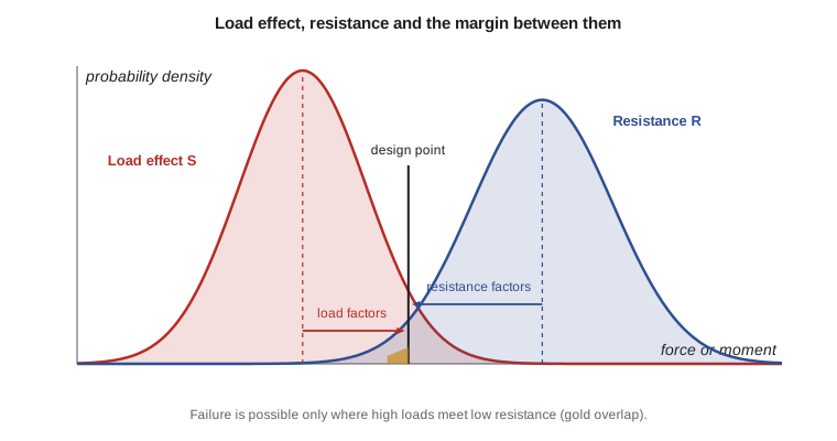
The figure shows the reasoning. Both the load effect and the resistance are random. The load factors push the design value of the load effect up into its upper tail, and the resistance factors pull the design value of the resistance down into its lower tail. As long as the factored resistance exceeds the factored load effect, the probability that the real load effect exceeds the real resistance is very small. Calibration studies chose the factors so that the reliability index, a measure of the distance between the two distributions, is about 3 to 3.5 for typical members over a 50-year life.
The single \(\phi\) of ACI 318 has a clear physical logic as well. A member whose steel yields well before the concrete crushes gives warning by large deflection and wide cracks, so it is given a high factor of 0.90. A column that fails by concrete crushing gives little warning and supports everything above it, so it gets 0.65 (or 0.75 with spiral reinforcement). The code decides which case applies from the net tensile strain in the extreme tension steel, as lesson 3 explains.
| Action | ACI 318 strength reduction factor φ |
|---|---|
| Tension-controlled flexure and axial tension | 0.90 |
| Shear and torsion | 0.75 |
| Compression-controlled, tied | 0.65 |
| Compression-controlled, spiral | 0.75 |
| Bearing on concrete | 0.65 |
| Plain concrete | 0.60 |
Loads and load combinations
ASCE 7 defines nominal loads: dead load D, live load L, roof live load Lr, snow load S, rain load R, wind load W and earthquake load E. Live loads come from tables; for example, 50 psf for office floors and 40 psf for passenger vehicle garages, with partition loads added where partitions can move. The strength (LRFD) load combinations take one principal load with its full factor plus companion loads with smaller factors, because the maximum values of different loads are unlikely to occur together.
| Case | Principal loads | Companion loads |
|---|---|---|
| 1 | 1.4D | — |
| 2 | 1.2D + 1.6L | 0.5(Lr or S or R) |
| 3 | 1.2D + 1.6(Lr or S or R) | L or 0.5W |
| 4 | 1.2D + 1.0W | L + 0.5(Lr or S or R) |
| 5 | 0.9D + 1.0W | — |
| 6 | 1.2D + Ev + Eh | L + 0.15S |
| 7 | 0.9D − Ev + Eh | — |
Risk categories in ASCE 7 scale the snow, wind and earthquake loads according to the consequences of failure. A municipal operations center that houses snow-clearing equipment and emergency coordination is likely to be Risk Category IV as an essential facility, which increases these loads; the team confirms the category with the city before calculating the environmental loads.
Design forces for two members
Owen starts with two members. The office floor beam spans 25 ft between columns and carries a 16 ft wide strip of floor. Its service dead load, including the slab, the beam stem, ceilings, services and a partition allowance, is 1.40 kip/ft; the live load is 50 psf × 16 ft = 0.80 kip/ft. The garage roof beam spans 30 ft over the parking level and carries a dead load of 1.25 kip/ft and a snow load of 0.90 kip/ft. For a first estimate he treats both as simply supported; the continuous analysis of CIV-321 refines the moments later.
Worked problem
Factored load on the office floor beam
Find the governing factored uniform load, moment and shear for the office floor beam (D = 1.40 kip/ft, L = 0.80 kip/ft, span 25 ft, simply supported).
Show solution
- Combination 1 gives
- \[w_u = 1.4(1.40) = 1.96\ \text{kip/ft}\]
- Combination 2 with L as the principal load gives
- \[w_u = 1.2(1.40) + 1.6(0.80) = 1.68 + 1.28 = 2.96\ \text{kip/ft}\]
- There is no snow on an interior floor, so the companion load adds nothing. Combination 2 governs. The factored moment and shear are
- \[M_u = \frac{w_u L^2}{8} = \frac{2.96(25)^2}{8} = 231\ \text{kip·ft} \qquad V_u = \frac{w_u L}{2} = 37.0\ \text{kips}\]
Answer: \(w_u = 2.96\) kip/ft, \(M_u = 231\) kip·ft and \(V_u = 37.0\) kips. These values are used to design the beam in lessons 3, 5 and 6.
Sofia's program repeats the calculation for both members so that the governing combination can be read at a glance. For the garage roof beam the snow case governs, as expected for a roof in a snowy climate.
# ASCE 7 strength (LRFD) combinations for two members of the operations center
# Service loads per foot of beam (kip/ft)
members = {
    "office floor beam": {"D": 1.40, "L": 0.80, "S": 0.0,  "span": 25.0},
    "garage roof beam":  {"D": 1.25, "L": 0.0,  "S": 0.90, "span": 30.0},
}
# (name, factor on D, factor on L, factor on S)
combos = [
    ("1  1.4D",              1.4, 0.0, 0.0),
    ("2  1.2D + 1.6L + 0.5S", 1.2, 1.6, 0.5),
    ("3  1.2D + 1.6S + 1.0L", 1.2, 1.0, 1.6),
]
for name, m in members.items():
    print(name, "- span", m["span"], "ft")
    best = None
    for label, fd, fl, fs in combos:
        w = fd * m["D"] + fl * m["L"] + fs * m["S"]
        print(f"   {label:22s} wu = {w:5.2f} kip/ft")
        if best is None or w > best[1]:
            best = (label, w)
    w = best[1]; L = m["span"]
    Mu = w * L**2 / 8; Vu = w * L / 2
print(f" governs: {best[0].strip()} Mu = {Mu:.0f} kip-ft Vu = {Vu:.1f} kips")office floor beam - span 25.0 ft 1 1.4D wu = 1.96 kip/ft 2 1.2D + 1.6L + 0.5S wu = 2.96 kip/ft 3 1.2D + 1.6S + 1.0L wu = 2.48 kip/ft governs: 2 1.2D + 1.6L + 0.5S Mu = 231 kip-ft Vu = 37.0 kips garage roof beam - span 30.0 ft 1 1.4D wu = 1.75 kip/ft 2 1.2D + 1.6L + 0.5S wu = 1.95 kip/ft 3 1.2D + 1.6S + 1.0L wu = 2.94 kip/ft governs: 3 1.2D + 1.6S + 1.0L Mu = 331 kip-ft Vu = 44.1 kips
Two features of the output are worth noting. First, the factored loads are 30 to 40 percent above the service loads, which is the margin the load factors provide. Second, the governing combination changes from member to member, which is why design software checks every combination at every section. ACI 318 adds no further load factor; all of its safety beyond the load factors lies in \(\phi\).
Serviceability and durability from the start
Strength is only half of the design. Under service loads the beam must not deflect enough to crack partitions, and its cracks must stay narrow enough not to look alarming or admit water and chlorides. ACI 318 controls deflection either by minimum member thicknesses or by calculated deflections compared with span-based limits, and it controls cracking by the spacing of reinforcement. Lesson 5 covers both.
Durability decisions are made early because they set the concrete strength and cover. ACI 318 assigns exposure categories and classes. The office interior is not exposed, but the garage parking level is exposed to de-icing chemicals tracked in on vehicles, which puts it in freezing-and-thawing class F3 and corrosion class C2. Those classes require a minimum strength of 5,000 psi, a low water-cementitious materials ratio and air entrainment, and the parking structure guide ACI 362 recommends larger cover, sealers or membranes and good drainage. The team uses 4,000 psi for the office and 5,000 psi for the garage.
Common mistakes
MistakeUsing \(\phi = 0.90\) for every member without checking the strain.
Instead\(\phi\) depends on the net tensile strain at failure; a member with too much steel or a column gets a smaller factor.
MistakeDesigning for service loads at the strength limit state.
InsteadStrength checks always use factored loads; service loads are for deflection and cracking.
MistakeAssuming the largest load factor always gives the governing combination.
InsteadCheck every combination; the governing one depends on the ratio of the loads, as the roof beam shows.
MistakeLeaving durability until the details are drawn.
InsteadExposure sets strength, cover and air content, which change member sizes, so decide it first.
Summary and key terms
- Reinforced concrete combines concrete for compression with deformed steel bars for tension; cracking in service is expected and controlled.
- ACI 318 with ASCE 7 loads governs design in the United States; the edition used is the one referenced by the adopted building code.
- Limit states design checks ultimate (strength) limit states with factored loads and serviceability limit states with service loads.
- ACI 318 multiplies the nominal strength by \(\phi\), which depends on the failure mode: 0.90 tension-controlled, 0.75 shear, 0.65 tied compression.
- For the office beam, \(w_u = 1.2D + 1.6L = 2.96\) kip/ft and \(M_u = 231\) kip·ft.
- Exposure classes decide concrete strength, air content and cover, so they are set at the start of design.
- Limit state
- A condition beyond which a structure no longer fulfills a design requirement.
- Ultimate limit state
- A limit state involving collapse or failure, checked with factored loads.
- Serviceability limit state
- A limit state affecting function or appearance in normal use, checked with service loads.
- Design strength
- The nominal strength multiplied by the strength reduction factor φ.
- Load combination
- A set of loads, each multiplied by a factor, that may act together.
- Companion load
- A load acting with the principal load in a combination, given a reduced factor.
- Exposure class
- A category describing the environment of a concrete element, used to set durability requirements.
- Deformed bar
- A reinforcing bar with surface ribs that interlock with concrete.
Practice problems
Work each problem on paper first, then reveal the answer to check.
A floor beam carries D = 1.0 kip/ft and L = 0.70 kip/ft. Find \(w_u\).
Show answer
Combination 2: \(1.2(1.0) + 1.6(0.70) = 2.32\) kip/ft; combination 1 gives 1.40 kip/ft, so 2.32 kip/ft governs.
Why is \(\phi\) smaller for a tied column than for a beam?
Show answer
Column failure by crushing is sudden and supports everything above; beams that yield give warning.
Name one ultimate and one serviceability limit state for a parking slab.
Show answer
Ultimate: flexural or punching shear failure. Serviceability: wide cracks that let chlorides reach the steel, or excessive deflection.
For a roof beam with D = 0.8 kip/ft and S = 0.6 kip/ft, which combination governs?
Show answer
Combination 3: \(1.2(0.8) + 1.6(0.6) = 1.92\) kip/ft versus combination 1, 1.12 kip/ft. Combination 3 governs.
Why are companion loads given smaller factors than principal loads?
Show answer
The maximum values of different variable loads are unlikely to occur at the same time.
Lesson quiz · 5 questions
Score 60% or more to complete this lesson.
Create a free account to save your progress, take quizzes and earn a certificate.