
CIV-221 · Lesson 6 of 12 · 26 min
Shear stresses in beams
Most beams carry shear force as well as bending moment. The bending moment produces the normal stresses of lesson 5; the shear force produces shear stresses, which are usually smaller but can govern short heavily loaded beams, timber beams (which are weak in shear along the grain), the webs of thin steel girders, and above all the connections that hold built-up members together. This lesson derives the shear stress formula, shows how shear stress is distributed over common sections, and uses the idea of shear flow to space nails, bolts and welds.
Why horizontal shear exists
Stack several loose boards on two supports and load them at midspan. Each board bends on its own, and their ends slide past one another, so the stack is flexible and weak. Glue the boards together and the stack behaves as a single deep beam, far stiffer and stronger, because the glue now prevents the sliding. The glue lines are carrying horizontal shear stress.
The same thing happens inside any solid beam. Where the bending moment changes along the span, the compressive force in the top part of the beam on one side of an element is larger than on the other side. Something must balance the difference, and that something is a shear force on the horizontal plane that separates the top part from the rest. By the equilibrium of a small element, a horizontal shear stress at a point is always accompanied by an equal vertical shear stress. So the vertical shear force \(V\) on a cross-section and the horizontal shear along the beam are two views of the same stresses.
The shear formula
Consider a short length \(dx\) of beam and the part of it above some level \(y_1\). The bending stresses on its two ends are \(-My/I\) and \(-(M + dM)y/I\). Their resultants differ by \((dM/I)\int y\,dA\), taken over the area above \(y_1\). That difference must be balanced by a horizontal shear stress \(\tau\) acting over the width \(t\) of the cut, on an area \(t\,dx\). Setting the forces equal and using \(dM/dx = V\) gives the shear formula:
Here \(V\) is the shear force at the section, \(I\) is the second moment of area of the whole section about the neutral axis, \(t\) is the width of the section at the level where the stress is wanted, and \(Q\) is the first moment of area of the part of the section beyond that level, taken about the neutral axis:
where \(A'\) is the area above (or below) the level and \(\bar{y}'\) is the distance from the neutral axis to its centroid. \(Q\) is zero at the top and bottom surfaces, where there is no area beyond, and it is largest at the neutral axis. So the shear stress is zero at the extreme fibers, exactly where the bending stress is largest, and usually peaks at the neutral axis, where the bending stress is zero.
The formula assumes the shear stress is uniform across the width \(t\). That is accurate for narrow rectangles and thin webs, and less accurate for very wide, shallow sections, where the true stress at the edges can be noticeably higher than the formula predicts. For design purposes it is the standard tool.
Distribution in a rectangular section
For a rectangle of width \(b\) and depth \(h\), the area above a level \(y\) is \(A' = b(h/2 - y)\), with centroid at \(\bar{y}' = (h/2 + y)/2\). So \(Q = (b/2)(h^2/4 - y^2)\), and
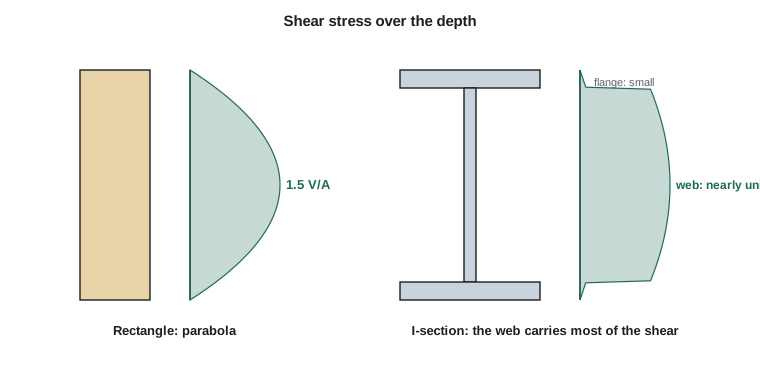
The distribution is a parabola, zero at the top and bottom and greatest at the neutral axis. Substituting \(I = bh^3/12\) at \(y = 0\):
The maximum is 50 % higher than the average shear stress \(V/A\). This result is used constantly in timber design, where horizontal shear (sometimes called rolling or longitudinal shear) often governs short, heavily loaded beams.
Worked problem
Shear in a glulam beam
A glued-laminated timber beam 130 mm wide and 456 mm deep spans 6.0 m and carries a uniform load of 18 kN/m. Find the maximum shear stress and the shear stress in the glue line 76 mm below the top.
Show solution
- Maximum shear at the supports: \(V = wL/2 = 18 \times 6/2 = 54\ \text{kN}\).
- \[\tau_{\max} = \frac{3}{2}\cdot\frac{54\,000}{130 \times 456} = 1.37\ \text{MPa}\]
- For the glue line: \(I = 130(456)^3/12 = 1\,027 \times 10^6\ \text{mm}^4\). The area above is \(A' = 130 \times 76 = 9\,880\ \text{mm}^2\), centroid \(228 - 38 = 190\ \text{mm}\) above the neutral axis, so \(Q = 1.877 \times 10^6\ \text{mm}^3\).
- \[\tau = \frac{V\,Q}{I\,t} = \frac{54\,000 \times 1.877 \times 10^6}{1\,027 \times 10^6 \times 130} = 0.76\ \text{MPa}\]
Answer: The maximum shear stress is 1.37 MPa at mid-depth; the glue line near the top carries 0.76 MPa. Both are compared with the shear resistance given in the timber design standard.
Distribution in I-sections and thin webs
In an I-shaped section the width changes abruptly at the junction of web and flange. Just inside the flange the width \(t\) is the full flange width, so \(\tau\) is small; just inside the web, \(t\) drops to the web thickness, so \(\tau\) jumps up by the ratio of the widths. Within the web the distribution is a shallow parabola with its peak at the neutral axis.
The web carries about 90 % or more of the vertical shear in a typical wide-flange beam, and the stress over it is nearly uniform. That is why steel design codes check shear on the web alone, using the approximation
where \(d\) is the overall depth and \(t_w\) the web thickness. In slender plate girders, the web may buckle in shear long before it yields, so deep girders are fitted with transverse stiffeners. Steel and bridge design courses cover these checks.
The flanges of an I-beam carry little vertical shear, but they do carry horizontal shear stresses flowing along their width, from the tips toward the web. Those horizontal flange stresses are what lead to the idea of the shear center, discussed at the end of this lesson.
Shear flow in built-up members
Built-up beams are made by joining pieces: boards nailed into a box beam, plates welded into a girder, a steel beam connected to a concrete slab by shear studs. The connectors must carry the horizontal shear that would otherwise make the pieces slide. The useful quantity is the shear flow \(q\), the shear force per unit length along the beam:
Here \(Q\) is the first moment of the part being held on (for example, one flange) about the neutral axis of the whole section. If connectors each able to carry a force \(F\) are spaced at a pitch \(s\) along the beam, they can carry a shear flow of \(F/s\) (or \(nF/s\) if there are \(n\) connectors in each row). The required spacing is therefore
Because \(q\) is proportional to \(V\), connectors can be spaced more widely near midspan, where shear is small, and must be closer near the supports. Welds are designed the same way: the shear flow at the web–flange junction divided by the strength of the weld per unit length gives the weld size or the length of intermittent welds.
Worked problem
Nail spacing in a box beam
A box beam is built from two flanges, each 200 mm × 40 mm, nailed to two webs, each 25 mm × 300 mm, so the overall section is 200 mm wide and 380 mm deep. The flanges sit on top of the webs. Each nail can carry 0.9 kN in shear. The beam carries a shear force of 12 kN. Find the maximum nail spacing, with one line of nails through the flange into each web.
Show solution
- \(I\) of the section: flanges \(2[200(40)^3/12 + 8\,000(170)^2] = 2[1.07 + 231.2] \times 10^6 = 464.5 \times 10^6\); webs \(2[25(300)^3/12] = 112.5 \times 10^6\). Total \(I = 577.0 \times 10^6\ \text{mm}^4\).
- \(Q\) for one flange: \(A' = 8\,000\ \text{mm}^2\), \(\bar{y}' = 170\ \text{mm}\), so \(Q = 1.36 \times 10^6\ \text{mm}^3\).
- \[q = \frac{V\,Q}{I} = \frac{12\,000 \times 1.36 \times 10^6}{577.0 \times 10^6} = 28.3\ \text{N/mm}\]
- Two lines of nails (one into each web) hold the flange: \(s \le 2 \times 900/28.3 = 63.6\ \text{mm}\).
Answer: Nails at about 60 mm spacing near the supports. Where the shear is lower, the spacing can be increased in proportion.
Worked problem
Bolt spacing in US customary units
A cover plate is bolted to the bottom flange of a steel beam. At the section considered, \(V = 40\ \text{kips}\), \(I\) of the combined section is \(2\,100\ \text{in.}^4\), and \(Q\) of the cover plate about the neutral axis is \(48\ \text{in.}^3\). Two bolts per row each carry 11 kips in shear. Find the maximum bolt pitch.
Show solution
- \[q = \frac{V\,Q}{I} = \frac{40 \times 48}{2\,100} = 0.914\ \text{kips/in.}\]
- \[s \le \frac{n\,F}{q} = \frac{2 \times 11}{0.914} = 24.1\ \text{in.}\]
Answer: A pitch of up to about 24 in. satisfies shear flow. Steel codes also limit the maximum pitch of fasteners on plates for other reasons, such as preventing local buckling of the plate between bolts and keeping out moisture, and these limits may govern.
Thin-walled open sections and the shear center
In thin-walled open sections, shear flow runs along the walls. In a channel loaded through its web, the horizontal shear flows in the two flanges point in opposite directions and form a couple. That couple twists the channel unless the load is applied at a particular point outside the web, the shear center. Only loads through the shear center bend a beam without twisting it.
For sections with two axes of symmetry, such as I-beams and rectangular tubes, the shear center coincides with the centroid, so no special care is needed. For channels, angles and Z-sections it does not. That is why channels used as lintels or purlins are often installed in back-to-back pairs or braced, and why a load hung from the toe of an angle produces twisting. Light-gauge steel purlins and girts, which are usually C- or Z-shaped, are designed with the shear center in mind.
Shear stress through the depth by code
The program below evaluates \(VQ/(It)\) at many levels through a symmetric I-section, showing the jump at the flange–web junction and the nearly uniform stress in the web. It also compares the peak with the simple \(V/(d\,t_w)\) approximation.
# Shear stress through the depth of a symmetric I-section (mm, N)
bf, tf, d, tw = 200.0, 15.0, 400.0, 9.0
V = 250e3
hw = d - 2 * tf
I = bf * d**3 / 12 - (bf - tw) * hw**3 / 12

def Q_above(y):                     # first moment of the area above level y (y from neutral axis)
    if y >= d / 2 - tf:             # inside the top flange
        return bf * (d / 2 - y) * (d / 2 + y) / 2
    Qf = bf * tf * (d / 2 - tf / 2)
    return Qf + tw * (d / 2 - tf - y) * (d / 2 - tf + y) / 2

def width(y):
    return bf if abs(y) > d / 2 - tf else tw

print(f"I = {I/1e6:.1f} x10^6 mm4")
for y in [200, 190, 185.01, 184.99, 150, 100, 50, 0]:
    tau = V * Q_above(y) / (I * width(y))
    where = "flange" if width(y) == bf else "web"
    print(f"y = {y:7.2f} mm ({where:6s})  tau = {tau:6.1f} MPa")
print(f"Approximation V/(d*tw) = {V / (d * tw):.1f} MPa")
web_force = sum(V * Q_above(y) / I * 0.5 for y in [i * 0.5 - (hw / 2) + 0.25 for i in range(int(hw / 0.5))])
print(f"Share of V carried by the web = {web_force / V:.1%}")I = 260.4 x10^6 mm4 y = 200.00 mm (flange) tau = 0.0 MPa y = 190.00 mm (flange) tau = 1.9 MPa y = 185.01 mm (flange) tau = 2.8 MPa y = 184.99 mm (web ) tau = 61.6 MPa y = 150.00 mm (web ) tau = 67.2 MPa y = 100.00 mm (web ) tau = 73.2 MPa y = 50.00 mm (web ) tau = 76.8 MPa y = 0.00 mm (web ) tau = 78.0 MPa Approximation V/(d*tw) = 69.4 MPa Share of V carried by the web = 96.6%
The stress jumps from a few megapascals in the flange to over 60 MPa in the web at the junction, and the web carries the vast majority of the shear. The simple approximation is about 11 % below the true peak at the neutral axis, but it is close to the average stress over the web, which carries about 97 % of the shear here. Design codes calibrate their shear resistances to the simple formula, so it is the one to use in a code check.
Common mistakes
MistakeUsing the width of the flange for \(t\) when finding the stress in the web.
Instead\(t\) is the width at the level where you want the stress. In the web it is the web thickness.
MistakeTaking \(Q\) about the bottom of the section or about the centroid of \(A'\).
Instead\(Q = A'\bar{y}'\), where \(\bar{y}'\) is measured from the neutral axis of the whole section.
MistakeSpacing connectors uniformly using the shear at midspan.
InsteadShear flow follows the shear diagram. Space connectors for the largest shear, usually near the supports, or vary the spacing.
MistakeAssuming a channel loaded through its web will not twist.
InsteadOnly loads through the shear center avoid twisting; for a channel it lies outside the web.
Summary and key terms
- Shear force produces both vertical and horizontal shear stresses of equal magnitude at any point.
- The shear formula is \(\tau = VQ/(It)\), with \(Q\) the first moment of the area beyond the level considered.
- Shear stress is zero at the extreme fibers and usually greatest at the neutral axis.
- For a rectangle, \(\tau_{\max} = 1.5V/A\).
- In I-sections the web carries nearly all the shear; codes use \(V/(d\,t_w)\).
- Shear flow \(q = VQ/I\) sets the spacing of nails, bolts and welds in built-up members: \(s \le nF/q\).
- Loads must pass through the shear center to avoid twisting thin-walled open sections.
- Horizontal shear
- Shear stress on planes parallel to the beam axis, equal to the vertical shear stress at the same point.
- First moment of area
- Q, the area beyond a level times the distance from the neutral axis to its centroid.
- Shear formula
- tau = VQ/(It), the shear stress at a level in a beam.
- Shear flow
- Shear force per unit length along a beam, q = VQ/I.
- Pitch
- The spacing of connectors along a member.
- Built-up member
- A member made by connecting separate pieces with nails, bolts, welds or adhesive.
- Shear center
- The point through which a transverse load must pass to bend a section without twisting it.
Practice problems
Work each problem on paper first, then reveal the answer to check.
A 100 × 300 mm rectangular beam carries \(V = 45\ \text{kN}\). Find \(\tau_{\max}\).
Show answer
\(1.5 \times 45\,000/30\,000 = 2.25\ \text{MPa}\).
Where in a rectangular beam is the shear stress zero?
Show answer
At the top and bottom surfaces, where \(Q = 0\).
A steel beam has \(d = 460\ \text{mm}\), \(t_w = 9\ \text{mm}\) and carries \(V = 300\ \text{kN}\). Estimate the web shear stress.
Show answer
\(300\,000/(460 \times 9) = 72.5\ \text{MPa}\).
Shear flow at a joint is 40 N/mm and each nail carries 800 N. With one line of nails, what spacing is needed?
Show answer
\(s \le 800/40 = 20\ \text{mm}\), which is very close; a stronger connection or two lines would be used.
Why can nail spacing increase toward midspan of a uniformly loaded simple beam?
Show answer
The shear force, and so the shear flow, falls toward zero at midspan.
Why is the shear center of an I-beam at its centroid?
Show answer
The section has two axes of symmetry, so the flange shear flows balance and produce no net twisting.
Lesson quiz · 5 questions
Score 60% or more to complete this lesson.
Create a free account to save your progress, take quizzes and earn a certificate.