
CIV-221 · Lesson 2 of 12 · 30 min
Axially loaded members
Axially loaded members are everywhere in civil engineering: truss chords and diagonals, hanger rods, tie-backs for retaining walls, columns, piles and post-tensioning tendons. Lesson 1 showed how to find the stress in such a member. This lesson finds how much it stretches or shortens, which matters for serviceability and for fit-up during construction, and then uses deformation to solve problems that equilibrium alone cannot: statically indeterminate members and members restrained against thermal movement.
Elongation of a prismatic bar
Combine the three ingredients from lesson 1. Equilibrium gives the internal force \(P\) and the stress \(\sigma = P/A\). The material law gives the strain \(\varepsilon = \sigma/E\). Geometry gives the elongation \(\delta = \varepsilon L\). Putting them together:
The product \(AE\) is called the axial rigidity. Doubling the area or using a material twice as stiff halves the elongation. The ratio \(AE/L\) is the axial stiffness \(k\), the force needed to produce a unit elongation, so the bar behaves like a spring with \(P = k\,\delta\). Thinking of members as springs is a powerful idea, and it is the starting point of the stiffness method used in structural analysis software.
Use a consistent sign convention: tension and elongation positive, compression and shortening negative. Then a compressive force automatically gives a negative \(\delta\).
Bars with several segments
When the load, area or material changes along the bar, split it into segments in which all three are constant, find the internal force in each segment with the method of sections, and add the elongations:
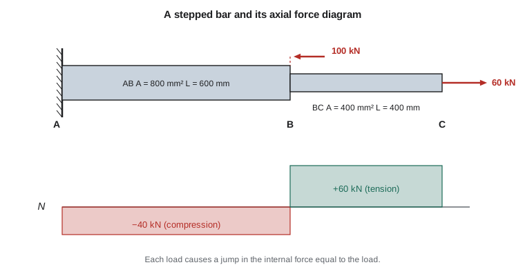
Drawing an axial force diagram, a plot of internal force along the bar, makes the bookkeeping much easier. Each external load causes a jump in the diagram equal to the load.
Worked problem
A stepped steel bar
A steel bar (\(E = 200\ \text{GPa}\)) is fixed to a wall at A. Segment AB is 600 mm long with area 800 mm\(^2\); segment BC is 400 mm long with area 400 mm\(^2\). A load of 60 kN acts to the right at C, and a load of 100 kN acts to the left at B. Find the axial force in each segment and the displacement of C.
Show solution
- Cut through BC and look at the right-hand piece: \(P_{BC} = +60\ \text{kN}\) (tension).
- Cut through AB and look at everything to the right of the cut: \(P_{AB} = 60 - 100 = -40\ \text{kN}\) (compression).
- \[\delta_{AB} = \frac{(-40\,000)(600)}{(800)(200\,000)} = -0.150\ \text{mm}\]
- \[\delta_{BC} = \frac{(60\,000)(400)}{(400)(200\,000)} = +0.300\ \text{mm}\]
- Displacement of C relative to the fixed wall: \(\delta_C = -0.150 + 0.300 = +0.150\ \text{mm}\).
Answer: AB is in compression (\(-40\) kN), BC in tension (60 kN), and C moves 0.150 mm to the right.
When the area or the internal force varies continuously, the sum becomes an integral, \(\delta = \int_0^L P(x)\,dx / [A(x)\,E]\). A classic case is a tall hanging bar or cable under its own weight: the internal force grows linearly from zero at the bottom to the full weight at the top, and the elongation works out to half of what it would be if the whole weight hung from the bottom end. Tapered members, such as some light poles and piles, also need the integral form.
Statically indeterminate axial members
A member is statically indeterminate when equilibrium equations alone cannot give all the forces. A bar fixed between two rigid walls and loaded in the middle is the simplest example: there are two unknown reactions but only one useful equilibrium equation. A reinforced concrete column, in which steel bars and concrete share a load, is another.
The extra equations come from compatibility, a statement about how the deformations must fit together. The method has four steps that never change:
- Equilibrium. Write the equilibrium equations in terms of the unknown forces.
- Compatibility. Write a geometric condition the deformations must satisfy, such as the total elongation being zero between fixed walls, or two parts shortening by the same amount.
- Force–deformation. Replace each deformation with \(PL/AE\).
- Solve the equations together, then check that the answers make physical sense.
Worked problem
A bar between two walls
A uniform bar of length \(L\) is fixed at both ends A and B. A load \(P\) acts to the right at a point C, a distance \(a\) from A and \(b\) from B (\(a + b = L\)). Find the reactions.
Show solution
- Let \(R_A\) and \(R_B\) be the reactions, both pointing left. Equilibrium: \(R_A + R_B = P\).
- Segment AC is in tension with force \(R_A\); segment CB is in compression with force \(R_B\).
- Compatibility: the walls do not move, so the total elongation is zero:
- \[\frac{R_A\,a}{AE} - \frac{R_B\,b}{AE} = 0 \quad\Rightarrow\quad R_A\,a = R_B\,b\]
- Solving with equilibrium: \(R_A = P\,b/L\) and \(R_B = P\,a/L\).
Answer: \(R_A = Pb/L\), \(R_B = Pa/L\). The nearer wall takes the larger share, because the shorter segment is stiffer.
Worked problem
A composite post
A short post is made of a steel tube (\(A_s = 1\,500\ \text{mm}^2\), \(E_s = 200\ \text{GPa}\)) filled with concrete (\(A_c = 18\,000\ \text{mm}^2\), \(E_c = 25\ \text{GPa}\)). A rigid cap plate applies 900 kN. Find the stress in each material.
Show solution
- Equilibrium: \(P_s + P_c = 900\ \text{kN}\).
- Compatibility: the cap is rigid, so both shorten equally: \(\delta_s = \delta_c\), which gives \(P_s/(A_sE_s) = P_c/(A_cE_c)\).
- Axial rigidities: \(A_sE_s = 1500 \times 200 = 300\,000\ \text{kN}\) and \(A_cE_c = 18\,000 \times 25 = 450\,000\ \text{kN}\) (with \(E\) in kN/mm\(^2\)).
- Each part carries load in proportion to its rigidity: \(P_s = 900 \times 300/750 = 360\ \text{kN}\) and \(P_c = 540\ \text{kN}\).
- \[\sigma_s = \frac{360\,000}{1500} = 240\ \text{MPa}, \qquad \sigma_c = \frac{540\,000}{18\,000} = 30\ \text{MPa}\]
Answer: Steel 240 MPa, concrete 30 MPa (both compression). The stresses are in the ratio \(E_s/E_c = 8\), because both materials have the same strain.
The composite post shows a general rule: when parts are forced to deform together, the stiffer part attracts more load. This is why reinforcing steel in a concrete column is so effective, and why a designer must think about stiffness, not just strength, when different materials work together. In real concrete members, creep and shrinkage gradually shift more of the load onto the steel over time, a refinement covered in concrete design courses.
Thermal stress
Most materials expand when heated. A free bar of length \(L\) whose temperature rises by \(\Delta T\) lengthens by
where \(\alpha\) is the coefficient of thermal expansion. For steel \(\alpha \approx 12 \times 10^{-6}\) per degree Celsius, and concrete is similar, which is one reason the two materials work well together. Aluminum expands about twice as much, roughly \(23 \times 10^{-6}\) per degree Celsius.
A free bar develops no stress when its temperature changes. Stress appears only when the movement is restrained. If a bar is fixed between rigid walls and heated, compatibility requires the thermal elongation to be canceled by a mechanical shortening, \(\alpha\,\Delta T\,L - PL/(AE) = 0\), so the restrained stress is
Note that the length and area cancel. A steel bar fully restrained and heated by 40 °C develops \(200\,000 \times 12 \times 10^{-6} \times 40 = 96\ \text{MPa}\) of compression, whatever its size. That is a large fraction of the yield strength, which is why bridges have expansion joints and bearings, why long concrete slabs have control joints, and why continuously welded rail must be installed at a carefully chosen neutral temperature to avoid buckling on hot days.
US bridges must accommodate a wide range: the AASHTO LRFD specifications give design temperature ranges that, in cold climates, exceed 70 °C (about 125 °F) for steel bridges. A 100 m steel span moving through 70 °C changes length by about \(12 \times 10^{-6} \times 70 \times 100\,000 \approx 84\ \text{mm}\), roughly 3.3 in., all of which the joints and bearings must accept.
Worked problem
A rod with a gap
A 2.0 m aluminum rod (\(E = 70\ \text{GPa}\), \(\alpha = 23 \times 10^{-6}/°\text{C}\), \(A = 600\ \text{mm}^2\)) is fixed at one end. At 15 °C there is a 1.0 mm gap between its free end and a rigid wall. Find the stress in the rod when the temperature rises to 75 °C.
Show solution
- Free thermal elongation: \(\delta_T = 23 \times 10^{-6} \times 60 \times 2000 = 2.76\ \text{mm}\).
- This exceeds the 1.0 mm gap, so the rod touches the wall and is compressed. The wall must push it back by \(2.76 - 1.00 = 1.76\ \text{mm}\).
- \[\frac{P\,L}{A\,E} = 1.76 \quad\Rightarrow\quad P = \frac{1.76 \times 600 \times 70\,000}{2000} = 36\,960\ \text{N}\]
- \[\sigma = -\frac{36\,960}{600} = -61.6\ \text{MPa}\]
Answer: The rod is in compression at about 62 MPa. Without the gap, the stress would have been \(E\alpha\Delta T = 96.6\ \text{MPa}\); the gap relieves part of it.
Worked problem
Thermal stress in US customary units
A steel rail (\(E = 29\,000\ \text{ksi}\), \(\alpha = 6.5 \times 10^{-6}/°\text{F}\)) is welded continuously and anchored at a neutral temperature of 95 °F. Estimate the stress on a cold night at \(-15\ °\text{F}\), assuming full restraint.
Show solution
- Temperature change: \(\Delta T = -15 - 95 = -110\ °\text{F}\).
- \[\sigma = -E\,\alpha\,\Delta T = -(29\,000)(6.5 \times 10^{-6})(-110) = +20.7\ \text{ksi}\]
Answer: About 20.7 ksi of tension. On a hot day above the neutral temperature, the stress reverses to compression, and that is when restrained rail can buckle sideways.
Stress concentrations
The formula \(\sigma = P/A\) gives the average stress on the net section. Near a hole, notch or sharp change in width, the actual stress peaks well above the average. The ratio of the peak stress to the nominal stress is the stress concentration factor \(K\):
For a small circular hole in a wide plate under tension, \(K\) is about 3. Fillets with generous radii have much lower factors than sharp corners. Charts of \(K\) for common geometries are published in handbooks such as Peterson's Stress Concentration Factors.
For ductile materials under steady load, stress concentrations are usually not critical: once the peak reaches yield, the material there yields and the load spreads to the surrounding area. Design codes for static strength of steel members therefore use the net-section average. But under repeated loading, fatigue cracks start at stress concentrations, and for brittle materials the peak governs failure. Highway bridges, crane runways and machine parts must be detailed with this in mind.
Computing a multi-segment bar
The bookkeeping for a bar with many segments is ideal for a short program. The code below takes the external loads and segment properties, builds the axial force in each segment by summing the loads to its right, and adds the elongations. It reproduces the stepped bar example and then adds a third segment.
# Axial force and displacement along a bar fixed at its left end
# Segments: (length mm, area mm^2, E MPa); loads at the right end of each segment (N, + to the right)
def solve_bar(segments, loads):
    total = 0.0
    for i, (L, A, E) in enumerate(segments):
        P = sum(loads[i:])               # internal force = sum of loads to the right of the cut
        d = P * L / (A * E)
        total += d
        print(f"Segment {i+1}: P = {P/1000:7.1f} kN   stress = {P/A:7.1f} MPa   "
              f"delta = {d:+.3f} mm   tip so far = {total:+.3f} mm")
    return total

print("Stepped bar from the example:")
solve_bar([(600, 800, 200e3), (400, 400, 200e3)], [-100e3, 60e3])

print("\nWith an aluminum extension carrying a further 20 kN:")
solve_bar([(600, 800, 200e3), (400, 400, 200e3), (300, 500, 70e3)], [-100e3, 60e3, 20e3])Stepped bar from the example: Segment 1: P = -40.0 kN stress = -50.0 MPa delta = -0.150 mm tip so far = -0.150 mm Segment 2: P = 60.0 kN stress = 150.0 MPa delta = +0.300 mm tip so far = +0.150 mm With an aluminum extension carrying a further 20 kN: Segment 1: P = -20.0 kN stress = -25.0 MPa delta = -0.075 mm tip so far = -0.075 mm Segment 2: P = 80.0 kN stress = 200.0 MPa delta = +0.400 mm tip so far = +0.325 mm Segment 3: P = 20.0 kN stress = 40.0 MPa delta = +0.171 mm tip so far = +0.496 mm
Note that adding a load at the far end changes the force in every segment to its left. That is the essence of the method of sections, and the program makes it hard to forget.
Common mistakes
MistakeUsing the external load at a section instead of the internal force in each segment.
InsteadCut each segment and sum the loads on one side. Draw the axial force diagram first.
MistakeIgnoring signs when adding segment elongations.
InsteadTreat tension and elongation as positive and compression as negative, so the sum gives the correct net movement.
MistakeTrying to solve an indeterminate problem with equilibrium alone.
InsteadCount unknowns and independent equilibrium equations. If unknowns exceed equations, add compatibility conditions.
MistakeAssuming a temperature change always causes stress.
InsteadOnly restrained thermal movement causes stress. A free member simply changes length.
Summary and key terms
- The elongation of a prismatic bar is \(\delta = PL/(AE)\); \(AE/L\) is its axial stiffness.
- For bars with several segments, add \(P_iL_i/(A_iE_i)\) using the internal force in each segment.
- Statically indeterminate problems combine equilibrium, compatibility and force–deformation relations.
- Parts forced to deform together share load in proportion to their axial rigidities.
- Free thermal elongation is \(\alpha\Delta TL\); a fully restrained bar develops \(\sigma = -E\alpha\Delta T\).
- Stress concentrations raise local peaks by a factor \(K\); they matter most for fatigue and brittle materials.
- Axial rigidity
- The product AE of a member's area and modulus.
- Axial stiffness
- Force needed per unit elongation, AE/L.
- Axial force diagram
- A plot of internal axial force along a member.
- Statically indeterminate
- Having more unknown forces than independent equilibrium equations.
- Compatibility
- A geometric condition that the deformations of connected parts must satisfy.
- Coefficient of thermal expansion
- Strain produced per degree of temperature change in a free material.
- Stress concentration factor
- The ratio of the peak local stress to the nominal stress at a discontinuity.
- Saint-Venant's principle
- The effect of how a load is applied dies out a short distance from the point of application.
Practice problems
Work each problem on paper first, then reveal the answer to check.
A 3.0 m steel rod (\(A = 300\ \text{mm}^2\)) carries 45 kN. How much does it stretch?
Show answer
\(\delta = 45\,000 \times 3000/(300 \times 200\,000) = 2.25\ \text{mm}\).
A bar between walls is loaded at its third point (\(a = L/3\)). What share does the nearer wall carry?
Show answer
\(R_A = Pb/L = 2P/3\).
Steel and aluminum bars of equal area share a load under a rigid plate. What fraction does the steel carry? (\(E_s = 200\), \(E_a = 70\) GPa)
Show answer
\(200/270 = 74\ \%\).
Find the restrained stress in a steel bar cooled by 30 °C.
Show answer
\(\sigma = -E\alpha\Delta T = -200\,000 \times 12 \times 10^{-6} \times (-30) = +72\ \text{MPa}\) (tension).
A plate with a hole has a nominal net-section stress of 80 MPa and \(K = 2.5\). What is the peak stress?
Show answer
\(2.5 \times 80 = 200\ \text{MPa}\).
Why does a hanging bar stretch only half as much under its own weight as under the same weight hung from its end?
Show answer
The internal force grows linearly from zero to the full weight, so its average value along the bar is half the weight.
Lesson quiz · 5 questions
Score 60% or more to complete this lesson.
Create a free account to save your progress, take quizzes and earn a certificate.