
CHE-499 · Lesson 9 of 12 · 22 min
Process control and P&IDs
A process flow diagram shows what the plant does at steady state. A piping and instrumentation diagram, or P&ID, shows how it is held there: every line with its size and specification, every valve, every instrument, every control loop, every relief device and every interlock. The brief asks for preliminary P&IDs of the reaction section. Jonah draws them, Liam develops the control strategy from CHE-374, and the hazard review of Lesson 10 is carried out on them. This lesson covers how a control strategy is built for a new plant, the conventions of P&IDs, and the design and tuning of the most important loop in the plant: the one that holds the oligomerization reactor's coolant temperature.
Control objectives
Liam starts with the objectives, in order of priority. First, safety: keep the plant within its safe operating limits, above all the oligomerization reactor's hot spot and the pressures in the hydrogen and ethylene systems. Second, environment: keep emissions and discharges within permit limits, which mostly means keeping the flare quiet and the fired heater burning cleanly. Third, product quality: keep the SAF within its specification. Fourth, production rate. Fifth, economics: minimize energy and losses. A control system that serves the lower objectives at the expense of the higher ones is badly designed, however smooth the plant runs on a good day.
Each objective becomes a set of controlled variables. Safety in the oligomerization section means the hot spot, which cannot be controlled directly because it moves along the tube, so the controlled variable is the coolant temperature, which sets it. Product quality means the jet's flash point and freezing point, which are measured slowly by analyzers or in the laboratory, so the columns control temperatures that infer them. Throughput means the hydrous ethanol feed rate, set by the operator.
Plantwide control
A plant with recycles and heat integration has to be controlled as a whole, not loop by loop. Liam follows the plantwide procedure CHE-374 described. He fixes the throughput manipulator, the ethanol feed flow controller at the front of the plant, and builds the inventory control outward from it in the direction of flow, so that each section takes what the section before it sends. He makes sure every recycle loop has a flow controlled somewhere in it, to avoid the snowball effect, in which a small disturbance makes recycle flows grow without limit. In the oligomerization loop, the recycle compressor runs at a controlled flow, and the purge is set on flow ratio to the recycle. Finally, he checks that every component has a way to leave or be consumed: ethane by the purge, water by the quench, oxygenates by the guard beds and stripper purge, heavy oligomers by the jet column bottoms.
| Section | Controlled variable | Manipulated variable | Notes |
|---|---|---|---|
| 100 Dehydration | Bed inlet temperatures | Fired heater coil outlet temperature (cascade to fuel flow) | Feed flow is the throughput manipulator |
| 200 Quench and compression | Compressor suction pressure | Spillback and cylinder unloaders | Sets the dehydration section pressure |
| 300 Oligomerization | Coolant (drum) temperature, via drum pressure | Steam export valve | Most critical loop in the plant |
| 300 Oligomerization | Ethylene fraction in reactor feed | Diluent recycle flow | Limits heat release per tube |
| 400 Hydrogenation | Hydrogen-to-olefin ratio | Hydrogen flow (ratio to olefin flow) | Ensures saturation with 10 % excess |
| 500 Fractionation | Jet column tray temperature | Reflux flow | Infers final boiling point; analyzer trims |
The oligomerization reactor coolant loop
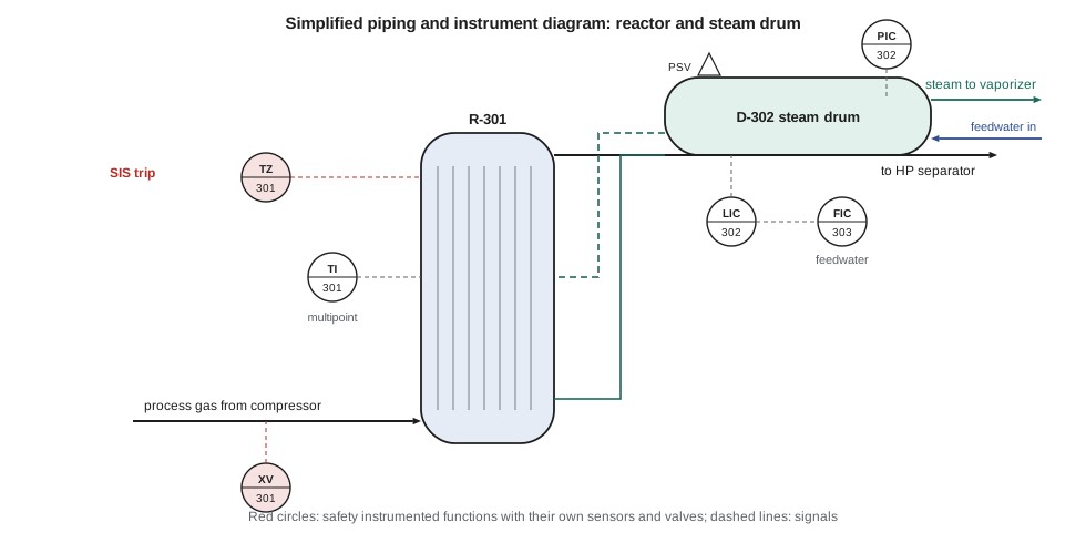
Lesson 5 showed that the hot spot rises by about 2.5 K for every kelvin of coolant temperature. The coolant is boiling water, so its temperature is fixed by the steam drum pressure. The drum pressure in turn is controlled by the valve that lets steam leave the drum to the feed vaporizer and the site header: open the valve and the pressure, and with it the boiling temperature, falls. Holding drum pressure tightly therefore holds the reactor tubes' wall temperature tightly, which is what the reactor's stability depends on.
Liam estimates the loop's dynamics from the drum's water and metal inventory and the valve characteristic, and checks the order of magnitude against a step test Theo arranges on one of the site's boiler drums: a first-order-plus-dead-time response with a gain of about −0.4 K per percent of valve opening, a time constant of about 90 s and a dead time of about 12 s. He tunes a PI controller by the SIMC rules, choosing the closed-loop time constant τc as the tuning knob:
# Steam drum pressure control on an oligomerization reactor: FOPDT model, SIMC PI tuning, closed-loop tests
# Process: steam export valve position (%) -> drum saturation temperature (C), linearized near 180 C
K, tau, theta = -0.40, 90.0, 12.0      # C per % valve (opening the valve lowers pressure), s, s (illustrative step test)
dt, t_end = 0.5, 900.0
def simc(tc):
    Kc = tau / (K * (tc + theta)); tI = min(tau, 4 * (tc + theta))
    return Kc, tI
def run(Kc, tI, sp_step=0.0, dist=0.0, t_dist=300.0):
    n = int(t_end / dt); delay = int(theta / dt)
    u_hist = [0.0] * (delay + 1)
    y, integ, u, iae, peak = 0.0, 0.0, 0.0, 0.0, 0.0
    for i in range(n):
        t = i * dt
        sp = sp_step if t >= 30 else 0.0
        e = sp - y
        integ += e * dt
        u = Kc * (e + integ / tI)
        u = max(-30.0, min(30.0, u))            # valve moves at most 30 % from its normal position
        u_hist.append(u)
        d = dist if t >= t_dist else 0.0         # extra reactor heat, as C of drum temperature at steady state
        y += dt / tau * (K * u_hist[-1 - delay] + d - y)
        iae += abs(e) * dt
        if t >= t_dist and dist: peak = max(peak, abs(y - sp))
    return y, iae, peak
for name, tc in (('tight (tc = theta)', theta), ('moderate (tc = 3 theta)', 3 * theta), ('loose (tc = 8 theta)', 8 * theta)):
    Kc, tI = simc(tc)
    y1, iae1, _ = run(Kc, tI, sp_step=-2.0)
    y2, iae2, pk = run(Kc, tI, dist=4.0)
    print(f"{name:<24} Kc {Kc:6.2f} %/C, tauI {tI:5.0f} s | setpoint -2 C: IAE {iae1:5.0f} C s | "
          f"+10 % reactor heat: peak {pk:.2f} C, IAE {iae2:4.0f} C s")
# The hot spot moves about 2.5 C per C of coolant (Lesson 5), so a 1 C drum deviation is a 2.5 C hot-spot deviation
Kc, tI = simc(3 * theta); _, _, pk = run(Kc, tI, dist=4.0)
print(f"moderate tuning: hot spot deviation about {2.5*pk:.1f} C during the heat upset")
# Hydrogen ratio control: hydrogen flow set by measured olefin flow times a ratio with 10 % excess
olefin = 36.0                            # kmol/h, from the balance
for change in (-0.2, 0.0, 0.2):
f = olefin * (1 + change); print(f"olefin {f:5.1f} kmol/h -> hydrogen setpoint {1.10*f:5.1f} kmol/h")tight (tc = theta) Kc -9.37 %/C, tauI 90 s | setpoint -2 C: IAE 53 C s | +10 % reactor heat: peak 0.87 C, IAE 96 C s moderate (tc = 3 theta) Kc -4.69 %/C, tauI 90 s | setpoint -2 C: IAE 96 C s | +10 % reactor heat: peak 1.18 C, IAE 192 C s loose (tc = 8 theta) Kc -2.08 %/C, tauI 90 s | setpoint -2 C: IAE 216 C s | +10 % reactor heat: peak 1.72 C, IAE 427 C s moderate tuning: hot spot deviation about 3.0 C during the heat upset olefin 28.8 kmol/h -> hydrogen setpoint 31.7 kmol/h olefin 36.0 kmol/h -> hydrogen setpoint 39.6 kmol/h olefin 43.2 kmol/h -> hydrogen setpoint 47.5 kmol/h
Tight tuning, with τc equal to the dead time, holds the drum temperature within about 0.9 K when the reactor's heat release jumps by 10 %, and moderate tuning, with τc three times the dead time, within about 1.2 K. Loose tuning lets it drift by 1.7 K. Liam chooses the moderate setting. It is less aggressive on the valve and more tolerant of errors in the model, which matter because the model is an estimate, not a test on the real drum. The 1.2 K deviation means a hot-spot excursion of about 3 K, well inside the 15 K margin Lesson 5 left below the 215 °C limit.
The drum also needs level control, because a drum that boils dry stops cooling the reactor and a drum that overfills sends water into the steam line. Boiler-drum level is notoriously tricky: when the steam flow increases suddenly, the pressure falls, the water swells with bubbles and the level rises even though water is being lost faster. Liam specifies three-element level control, in which the feedwater flow follows the steam flow directly, trimmed by the level controller, the arrangement used on most industrial boilers.
Reading and drawing P&IDs
P&IDs follow the symbols and identification letters of ANSI/ISA-5.1. An instrument tag's first letter names the measured variable (T for temperature, P for pressure, F for flow, L for level, A for analysis), and the following letters its functions (I for indicate, C for control, T for transmit, A for alarm, with H and L for high and low). TIC-301 is a temperature indicating controller in section 300; PAHH-302 is a pressure alarm high-high. A circle shows a field-mounted instrument; a circle with a bar across it, an instrument whose function is in the control system and visible to the operator. Lines with different dash patterns distinguish process piping, electrical signals and software links. Each line carries a number giving its size, service, sequence and piping specification, so that every pipe on the drawing can be found in the line list.
Jonah's first drafts are reviewed by Theo, who has spent two years reading Kingfisher's P&IDs. His comments are practical. Every control valve needs isolation valves and a bypass, or a decision recorded that it does not. Every vessel needs drains and vents. Every instrument that trips the plant must be testable on line, which means isolation and test connections. Every relief valve needs an isolation philosophy, since locked-open block valves under a relief valve are a common source of incidents when the locks are not managed. And the drawing should show the normal position of every manual valve, because an operator reading it at three in the morning will need to know.
Basic control and safety instrumented functions
The control loops in the table are the basic process control system, which keeps the plant running normally. Separately, the plant needs safety instrumented functions that act when the process control has failed. In the oligomerization section, a high-high hot-spot temperature from the multipoint thermocouples, or a low-low drum level, closes the reactor feed valve and opens a depressuring valve to the flare, stopping the reaction. These functions are designed to ANSI/ISA-61511 (the US adoption of IEC 61511), use their own sensors and valves independent of the control loops, and have a required reliability set in the hazard analysis of Lesson 10. The P&ID shows them with distinct symbols and tags so that nobody mistakes a trip for a control loop.
Alarms
Each important variable also has alarms, and alarm design deserves as much care as control design. An operator flooded with alarms during an upset cannot find the one that matters; several major incidents have been partly blamed on alarm floods. Liam follows the alarm management principles of ISA-18.2: every alarm must require an operator action, must have a defined response and enough time for it, and must be prioritized. The hot-spot high alarm, for example, is set 7 K below the trip, giving the operator time to reduce the feed or the ethylene fraction before the safety system acts.
Worked problem
Tuning by SIMC
A level loop has a process gain of 0.8 % per %, time constant 300 s and dead time 20 s. What PI settings does SIMC give for τc = 40 s?
Show solution
- \(K_c = 300 / (0.8 \times (40 + 20)) = 6.25\).
- \(4(\tau_c + \theta) = 240\) s, less than \(\tau = 300\) s, so \(\tau_I = 240\) s.
- Settings: \(K_c = 6.25\), \(\tau_I = 240\) s.
Answer: Kc = 6.25 and τI = 240 s. For a slow process, SIMC uses the shorter integral time to reject load disturbances faster.
Operability: start-up, shutdown and turndown
A control strategy must work outside normal operation too. The team writes a short start-up sequence for the reaction section, which exposes the coupling Lesson 7 warned about. The dehydration section is started first with imported steam in the feed vaporizer, making ethylene that is flared until it meets the purity needed for oligomerization. The oligomerization reactors are brought up with the drums at a lower pressure, and therefore a cooler coolant, than normal, with the ethylene fraction low, and both are raised slowly while the hot spots are watched. Only when the reactors are making steam does the feed vaporizer switch from imported steam. The P&IDs must show the start-up lines, the flare connections and the steam import valves this sequence needs. At 50 % turndown the per-pass conversion rises because the residence time is longer; the reactor runs with a lower coolant temperature to keep the conversion and hot spot near their design values.
Common mistakes
MistakeDesigning control loops one at a time.
InsteadBuild a plantwide strategy: throughput manipulator, inventory control, recycle flow control and component exits.
MistakeControlling a recycle loop by level and pressure only.
InsteadFix a flow in every recycle loop to avoid snowballing.
MistakeUsing the same sensor for control and for the safety trip.
InsteadSafety instrumented functions need independent sensors and final elements.
MistakeSingle-element level control on a boiling drum.
InsteadUse three-element control; swell and shrink fool a level-only controller.
MistakeAdding alarms on every variable.
InsteadAlarm only what needs an operator action, with time to act and a priority.
Summary and key terms
- Control objectives are ranked: safety, environment, quality, rate, economics.
- Plantwide control fixes a throughput manipulator, controls inventories in the direction of flow and fixes a flow in every recycle.
- The oligomerization coolant temperature, set by steam drum pressure, is the most critical loop.
- SIMC rules tune PI controllers from a first-order-plus-dead-time model, with τc as the single tuning choice.
- P&IDs follow ISA-5.1 and show every line, valve, instrument, loop, relief device and interlock.
- Safety instrumented functions are independent of control loops; alarms are designed to ISA-18.2 principles.
- P&ID
- Piping and instrumentation diagram showing lines, valves, instruments and controls.
- Throughput manipulator
- The variable chosen to set the production rate.
- Snowball effect
- Uncontrolled growth of recycle flows after a small disturbance.
- SIMC tuning
- Skogestad PI tuning rules based on a first-order-plus-dead-time model.
- Three-element control
- Drum level control using level, steam flow and feedwater flow.
- Safety instrumented function
- An automatic function that brings a process to a safe state when a hazard is detected.
- Alarm flood
- More alarms than an operator can handle during an upset.
Practice problems
Work each problem on paper first, then reveal the answer to check.
What does the tag LAHH-302 mean?
Show answer
Level alarm high-high, loop 302 in section 300.
Why is drum pressure, not hot-spot temperature, the controlled variable for the reactor?
Show answer
The hot spot moves and cannot be measured or manipulated directly; drum pressure sets coolant temperature.
A drum deviation of 2 K would cause what hot-spot deviation?
Show answer
About 5 K.
Why does a recycle loop need a fixed flow?
Show answer
To prevent the snowball effect.
Why does the start-up use imported steam?
Show answer
The vaporizer's normal heat comes from the oligomerization reactors, which are not yet running.
What is the purpose of the hot-spot high alarm being 7 K below the trip?
Show answer
To give the operator time to act before the safety system shuts the reactor down.
Lesson quiz · 5 questions
Score 60% or more to complete this lesson.
Create a free account to save your progress, take quizzes and earn a certificate.