
CHE-499 · Lesson 8 of 12 · 23 min
Equipment design and specification sheets
Once the flowsheet, the reactors, the separations and the heat exchanger network are settled, each piece of equipment must be given a size, a material, a design pressure and temperature, and a description precise enough for a vendor to quote and an estimator to price. The record of that work is the equipment list and a specification sheet, or data sheet, for each item. In a feasibility study the sizes are preliminary, accurate to perhaps 20 or 30 %, but they must be consistent: a column whose reboiler duty differs from the heat balance, or a vessel whose design pressure is below its relief set pressure, makes the cost estimate and the safety review worthless. This lesson shows how the team sized its main items and wrote their data sheets.
The equipment list
The equipment list is the index of the plant. Each item has a tag number that follows Kingfisher's convention, a letter for the type and a number beginning with the section: R-301 is the first oligomerization reactor, C-501 the naphtha splitter, K-201 the ethylene compressor, E-104 the feed vaporizer. For each item the list gives a short description, the governing size, the design conditions, the material and a reference to its data sheet. The ATJ plant's list has about 95 items, from the four dehydration beds to the small chemical injection pumps.
Liam, who will build the cost estimate from the list, asks the team to fill it in two passes. In the first pass every item gets a size from a shortcut, so that the factored estimate of Lesson 12 can start early, as the schedule of Lesson 1 assumed. In the second pass the major items, those whose cost is large or whose design is uncertain, get detailed sizing and full data sheets. About twenty items make up most of the purchased equipment cost: the reactors, the compressors, the fired heater, the columns, the large exchangers and the tanks.
Design pressure and temperature
Every item needs a design pressure and design temperature, the conditions its mechanical design must withstand, which are higher than the normal operating conditions. Kingfisher's standard sets the design pressure at the larger of 110 % of the maximum operating pressure or the maximum operating pressure plus 1.7 bar, and the design temperature at the maximum operating temperature plus 25 °C. Items that can be blocked in with a pump or compressor running must be designed for the shutoff pressure of that machine or protected by relief. These rules connect equipment design to the safety review: the relief valves of Lesson 10 are set at or below the design pressure, so the design pressure decides how often relief is needed.
The oligomerization section operates at about 30 bar(g), so its vessels are designed for about 35 bar(g); the dehydration beds operate at about 3 bar(g) and 450 °C, so they are designed for about 6 bar(g) and 475 °C. The jet column runs under vacuum and must also be designed for full vacuum, because a column that is cooled with its vents closed can collapse.
Materials of construction
Most of the plant is carbon steel, which suits dry hydrocarbons at moderate temperature. Three areas need more. The dehydration beds, reheaters and effluent line run at up to 475 °C, above the range where plain carbon steel keeps its strength in long service; a low-alloy chromium-molybdenum steel is specified. The quench water circuit and process water stripper carry water with dissolved carbon dioxide, acetic acid and acetaldehyde, which corrode carbon steel; their wetted parts are stainless steel 304L or 316L. The caustic wash tower and its circuit need attention to caustic cracking of welded carbon steel, which post-weld heat treatment prevents at the temperatures involved. Hydrogen service needs materials chosen with reference to the Nelson curves of API RP 941, though at 260 °C and the hydrogen partial pressures in the hydrogenation section carbon steel is acceptable.
Sizing the major items
The code sizes six representative items by the methods of CHE-446 and CHE-350, using the flows and duties from earlier lessons.
# Preliminary sizing for the equipment list: compressor, reactor shell, vaporizer, jet column, separator, tanks
import math
R = 8.314
# --- ethylene compressor: 1.8 to 31 bar(a) in three stages with intercooling to 40 C
n = 211.0 / 3600 * 1000          # mol/s (ethylene plus traces)
k, eta, T1 = 1.24, 0.78, 313.15
r = (31.0 / 1.8) ** (1 / 3)
e = (k - 1) / k
W1 = n * R * T1 / e * (r**e - 1) / eta          # W per stage (ideal gas, polytropic-style estimate)
T2 = T1 * (1 + (r**e - 1) / eta)
print(f"compressor: stage ratio {r:.2f}, {W1/1e3:.0f} kW per stage, {3*W1/1e3:.0f} kW total; discharge {T2-273.15:.0f} C")
# --- oligomerization reactor shell: 1,400 tubes, 38.1 mm OD, triangular pitch 1.25 OD, one pass
Nt, do = 1400, 0.0381
Db = do * (Nt / 0.319) ** (1 / 2.142)             # bundle diameter correlation (Kern/Coulson-Richardson constants)
print(f"reactor: bundle diameter {Db:.2f} m, shell about {Db+0.06:.2f} m; tube length 6 m")
# --- feed vaporizer: 10 bar(g) steam condensing at 184 C, feed boiling 110 to 145 C
Q, U = 4.63e6, 1000.0
dT1, dT2 = 184 - 110, 184 - 145
LMTD = (dT1 - dT2) / math.log(dT1 / dT2)
print(f"vaporizer: LMTD {LMTD:.1f} K, area {Q/(U*LMTD):.0f} m2 at U = {U:.0f} W/(m2 K)")
# --- jet column diameter from the Souders-Brown flooding velocity at the top, 0.3 bar(a), 200 C
D_kmol, Rr, Mv = 27.4, 0.41, 170.0
V = (Rr + 1) * D_kmol / 3600 * Mv                  # kg/s of gas
rho_v = 0.3e5 * Mv / 1000 / (R * 473.15); rho_l = 650.0
C = 0.07                                            # m/s, 600 mm tray spacing (illustrative)
u_f = C * math.sqrt((rho_l - rho_v) / rho_v)
A_net = V / rho_v / (0.80 * u_f); A = A_net / 0.88
print(f"jet column: top gas {V:.2f} kg/s, density {rho_v:.2f} kg/m3, flooding {u_f:.2f} m/s, diameter {math.sqrt(4*A/math.pi):.2f} m")
# --- high-pressure separator shell thickness: t = P R / (S E - 0.6 P) + corrosion allowance
P, Dv, S, E, CA = 3.5, 2.0, 138.0, 1.0, 3.0         # MPa design, m inside diameter, MPa allowable, joint efficiency, mm
t = P * (Dv * 1000 / 2) / (S * E - 0.6 * P) + CA
print(f"separator: shell {t:.1f} mm including {CA:.0f} mm corrosion allowance; next plate 30 mm")
# --- product tanks from the storage days in the design basis (working volume 85 % of nominal)
for name, tph, rho, days, ntank in (('SAF', 4.66, 760, 14, 2), ('naphtha', 0.72, 700, 10, 1), ('diesel', 0.60, 800, 10, 1)):
    V = tph * 1000 / rho * 24 * days / 0.85 / ntank
    Dt = (4 * V / (math.pi * 1.0)) ** (1 / 3)          # height equal to diameter
print(f"{name}: {ntank} x {V:.0f} m3 nominal, about {Dt:.1f} m diameter and height")compressor: stage ratio 2.58, 204 kW per stage, 611 kW total; discharge 121 C reactor: bundle diameter 1.91 m, shell about 1.97 m; tube length 6 m vaporizer: LMTD 54.6 K, area 85 m2 at U = 1000 W/(m2 K) jet column: top gas 1.82 kg/s, density 1.30 kg/m3, flooding 1.57 m/s, diameter 1.27 m separator: shell 28.8 mm including 3 mm corrosion allowance; next plate 30 mm SAF: 2 x 1212 m3 nominal, about 11.6 m diameter and height naphtha: 1 x 290 m3 nominal, about 7.2 m diameter and height diesel: 1 x 212 m3 nominal, about 6.5 m diameter and height
The ethylene compressor takes about 211 kmol/h from 1.8 to 31 bar(a) in three stages of ratio about 2.6, using about 200 kW per stage and 610 kW in total, with intercooling to 40 °C. Each stage discharges at about 120 °C. Jonah asks why the discharge temperature matters: above about 150 °C, traces of oxygenates and heavier olefins can polymerize and foul the compressor, so a ratio high enough to push discharge temperatures there would need more stages. A centrifugal compressor is too small for this flow at these heads; the team specifies a reciprocating machine, which suits low flows and high ratios, with a spare for the first stage, which has the most fouling risk. Reciprocating compressors need more maintenance than centrifugal ones, which the operating cost carries.
Each of the two oligomerization reactors has 1,400 tubes of 38.1 mm outside diameter (32 mm inside) on a triangular pitch 1.25 times the diameter. The bundle diameter correlation gives about 1.9 m, so the shell is about 2.0 m in diameter with 6 m tubes. The shell side carries boiling water at 10 bar(g) and the tube side process gas at 30 bar(g); the tube sheets, which separate the two, are among the most demanding parts of the mechanical design, and the reactor would be built by a vendor that specializes in such vessels.
The feed vaporizer condenses about 4.6 MW of reactor steam at 184 °C against the hydrous feed boiling between 110 and 145 °C. With an overall coefficient of about 1,000 W/(m²·K) for condensing steam against a boiling organic-water mixture, the log mean temperature difference of about 55 K gives an area of about 85 m². Riya specifies a kettle reboiler type with the steam in the tubes. A kettle allows vapor to disengage cleanly, and its large liquid inventory makes it tolerant of upsets in the steam supply.
The jet column, at 0.3 bar(a) at the top, carries about 1.8 kg/s of vapor with a density of only about 1.3 kg/m³. With a flooding coefficient of about 0.07 m/s for 600 mm tray spacing, the flooding velocity is about 1.6 m/s. Designing at 80 % of flooding, with 12 % of the area for downcomers, gives a diameter of about 1.3 m. Under vacuum the pressure drop per tray matters, because every tray adds to the bottom pressure and therefore the bottom temperature; Riya chooses structured packing in place of trays for that reason, with the same diameter as a first estimate.
The high-pressure separator, 2.0 m in diameter at a design pressure of 3.5 MPa, needs a shell about 26 mm thick by the code formula for a cylinder under internal pressure, plus a 3 mm corrosion allowance. The next standard plate is 30 mm.
The product tanks are sized from the storage days in the design basis. Two SAF tanks of about 1,200 m³ each, about 11.6 m in diameter and height, give 14 days of storage and allow one tank to be filling while the other is tested and released, since every batch must be certified before shipment. The naphtha and diesel tanks are smaller. All are fixed-roof tanks to API 650 with internal floating roofs for the naphtha, whose vapor pressure is highest.
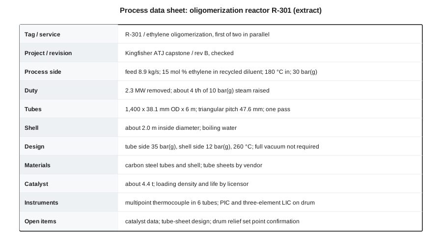
Writing a specification sheet
A process specification sheet tells the mechanical designer or vendor what the item must do; it does not design it for them. For an exchanger, it gives the fluids, flows, inlet and outlet temperatures, allowable pressure drops, fouling factors, design conditions and materials, and leaves the vendor to choose the tube count and layout that meet them. For a pump, it gives the liquid properties, flow, suction and discharge conditions and the net positive suction head available, and leaves the vendor to select the pump. Over-specifying, for example fixing an exchanger's tube count, prevents the vendor from offering a cheaper design that meets the duty.
The team uses Kingfisher's templates, which follow the layout of the standard industry forms. Each sheet has a revision block, and every revision is recorded in the change log of Lesson 2. Each sheet also has a notes section, where the team records open items: the reactor's catalyst loading density is a vendor item; the compressor's suction pressure depends on the final quench tower pressure drop. A sheet with no open items in a feasibility study is usually a sheet that has hidden its assumptions.
Worked problem
Checking a design pressure
The hydrogenation feed pump can deliver up to 45 bar(g) at shutoff. The hydrogenation reactor operates at 30 bar(g) and is designed for 35 bar(g). What must the design provide?
Show solution
- Shutoff pressure (45 bar(g)) exceeds the reactor design pressure (35 bar(g)).
- If the reactor outlet is blocked with the pump running, the reactor could be overpressured.
- Either design the reactor for 45 bar(g), or provide relief set at or below 35 bar(g) sized for the pump's flow at that pressure.
Answer: Relief on the reactor sized for the pump flow, or a higher design pressure. The choice is economic, but it must be made and recorded; Lesson 10 includes this case in the relief scenarios.
Utilities and offsites
Professor Marchetti's advice in Lesson 1 to design one section deeply and the rest adequately applies most clearly here. The cooling tower cell, the hot oil system, the nitrogen supply, the flare connection and the tank farm piping are sized by rule of thumb and listed with a single line each. The fired heater is specified by duty, fuel and emission limits and left to the heater vendor. The team states these simplifications in the report. An estimator who knows which items were sized in detail and which by shortcut can assign them different accuracy in the estimate.
Checking the equipment list
Before the list goes to Liam for costing, Ana checks it against the flowsheet in three ways. Every item on the process flow diagram appears in the list, and every item in the list appears on a drawing. Every duty in the list matches the heat balance and every flow matches the stream table. And every design pressure is consistent with the pressures upstream: no vessel can be overpressured by a source upstream of it unless it has relief. The checks find four errors: a missing spare pump, a heat duty from an earlier revision, a tank whose design temperature was below the summer maximum, and a vessel downstream of the hydrogen compressor that had no protection against the compressor's discharge pressure. Finding them now cost a few hours; finding them in detailed design would have cost weeks.
Common mistakes
MistakeSetting design pressure equal to operating pressure.
InsteadAdd the company's margin and check every source that could overpressure the item.
MistakeSpecifying carbon steel everywhere because it is cheapest.
InsteadCheck temperature, water chemistry, caustic and hydrogen service for each item.
MistakeFixing an exchanger's geometry on the process data sheet.
InsteadSpecify duty, conditions and limits; let the vendor optimize the geometry.
MistakeSizing a vacuum column on trays without checking pressure drop.
InsteadEvery tray raises the bottom temperature; consider packing.
MistakeHiding uncertain items by leaving no open notes.
InsteadRecord open items so the estimate and the next stage can treat them.
Summary and key terms
- The equipment list indexes every item with tag, size, design conditions, material and data sheet reference.
- Design pressure and temperature exceed operating values by company margins and must cover every overpressure source or be protected by relief.
- Materials follow temperature, corrosion, caustic and hydrogen service; most of the plant is carbon steel.
- Shortcut methods size compressors, reactors, exchangers, columns, vessels and tanks to feasibility accuracy.
- Process data sheets state what an item must do and leave the vendor to design it.
- Cross-checks of the list against the flowsheet, balances and pressures catch errors cheaply.
- Equipment list
- The index of all items in a plant with their key data.
- Data sheet
- A form specifying the process and mechanical requirements of one item.
- Design pressure
- The pressure an item is designed to withstand, above its operating pressure.
- Corrosion allowance
- Extra wall thickness provided for metal lost to corrosion over the design life.
- Kettle reboiler
- A shell-and-tube exchanger with a large liquid pool on the shell side.
- Flooding
- Column operation at which liquid can no longer flow down against the rising vapor.
- Shutoff pressure
- The maximum pressure a pump or compressor delivers against a closed outlet.
Practice problems
Work each problem on paper first, then reveal the answer to check.
What design pressure does Kingfisher's rule give for an operating pressure of 30 bar(g)?
Show answer
The larger of 33 and 31.7: 33 bar(g); the team rounds up to 35.
Why is the quench circuit made of stainless steel?
Show answer
Its water carries dissolved carbon dioxide and organic acids that corrode carbon steel.
Why was a reciprocating compressor chosen for ethylene?
Show answer
The flow is small and the pressure ratio high, outside the range of centrifugal machines.
What happens to the needed exchanger area if the LMTD halves at the same duty and U?
Show answer
It doubles.
Why does the jet column need a full vacuum design rating?
Show answer
It can collapse if cooled while blocked in under vacuum.
Why are there two SAF tanks rather than one?
Show answer
One can fill while the other is tested and released, since each batch must be certified.
Lesson quiz · 5 questions
Score 60% or more to complete this lesson.
Create a free account to save your progress, take quizzes and earn a certificate.