
CHE-499 · Lesson 7 of 12 · 23 min
Heat integration and utilities
Lesson 4 ended with an intuition: the ATJ plant needs about 10 MW of heat for its feed and reaction, but its exothermic reactors and quench give back nearly as much, so most of the purchased heat should be avoidable. This lesson tests that intuition with pinch analysis, the method CHE-446 taught on the ethyl acetate line, and then designs the utilities that remain. It is also where the carbon intensity of the product starts to be decided, because every megawatt of purchased heat carries emissions with it.
The stream data
Riya extracts the stream data from the balances of Lessons 4 to 6. Each hot stream needs cooling and each cold stream needs heating; each has a supply temperature, a target temperature and a duty. Streams that change phase are split into segments so that each can be treated as having a constant heat capacity flow rate. The feed vaporization, for example, is a cold stream of 5.0 MW between 110 and 145 °C, the range over which the hydrous ethanol and dilution water boil at the reactor feed pressure. The oligomerization reactor is a hot stream of 4.6 MW at 178 to 182 °C, the temperature at which its cooling water boils.
| Stream | From, °C | To, °C | Duty, MW |
|---|---|---|---|
| Dehydration effluent (gas cooling, then condensation) | 350 | 40 | 6.1 |
| Oligomerization reactor heat | 182 | 178 | 4.6 |
| Oligomerization loop effluent | 200 | 40 | 6.8 |
| Hydrogenation product | 260 | 60 | 1.9 |
| Column condensers and compressor intercoolers | 200 to 55 | 195 to 40 | 2.9 |
| Feed preheat and vaporization | 40 | 145 | 5.6 |
| Superheat to the first bed and interbed reheats | 145, 350 | 450 | 4.4 |
| Oligomerization loop reheat | 40 | 180 | 6.0 |
| Column reboilers and hydrogenation feed | 40 to 280 | 115 to 290 | 3.8 |
Two large streams deserve comment. The oligomerization loop circulates diluent and recycle gas that must be cooled to 40 °C to separate the liquid product and reheated to 180 °C to enter the reactors. That 6 to 7 MW is mostly exchanged between the loop's own outlet and inlet in a feed-effluent exchanger, as in any reactor loop. Pinch analysis treats it like any other pair of streams, but its size explains why the plant's total exchanger area will be larger than its utility duties suggest.
The problem table
The problem table algorithm finds the minimum utilities before any exchanger is designed. Hot stream temperatures are shifted down and cold stream temperatures up by half the minimum approach temperature ΔTmin, so that any hot stream can heat any cold stream in the same shifted interval. In each interval, the surplus or deficit of heat is the difference between the hot and cold heat capacity flow rates times the interval width. Cascading the surpluses from the top down, and adding just enough hot utility at the top to make every cascaded heat flow non-negative, gives the minimum hot utility; the heat left at the bottom is the minimum cooling. The pinch is where the cascaded heat flow is zero.
# Heat integration of the ATJ plant: problem table algorithm, then the high-temperature utility options
streams = [  # (name, supply C, target C, duty MW); hot streams cool, cold streams heat
    ('H1a dehydration effluent, gas', 350, 125, 1.66), ('H1b quench condensation', 125, 60, 4.00),
    ('H1c quench subcooling', 60, 40, 0.43), ('H2 oligomerization reactor heat', 182, 178, 4.63),
    ('H3 oligomerization effluent', 200, 40, 6.80), ('H4 hydrogenation product', 260, 60, 1.90),
    ('H5 jet column condenser', 200, 195, 0.90), ('H6 splitter condenser', 110, 105, 0.70),
    ('H7 stabilizer condenser', 60, 55, 0.80), ('H8 compressor intercoolers', 110, 40, 0.50),
    ('C1a feed preheat', 40, 110, 0.60), ('C1b feed vaporization', 110, 145, 5.00),
    ('C1c superheat to bed 1', 145, 450, 2.40), ('C2 interbed reheat', 350, 450, 2.00),
    ('C3 water stripper reboiler', 110, 115, 0.75), ('C4 jet column reboiler', 280, 290, 0.90),
    ('C5 stabilizer and splitter reboilers', 150, 185, 1.50), ('C6 hydrogenation feed', 40, 200, 0.66),
    ('C7 oligomerization loop reheat', 40, 180, 6.00)]
dTmin = 10.0
def problem_table(streams, dTmin):
    sh = []                                   # shifted temperatures: hot down, cold up by dTmin/2
    for n, ts, tt, q in streams:
        hot = ts > tt; s = -dTmin / 2 if hot else dTmin / 2
        sh.append((ts + s, tt + s, q / abs(tt - ts), hot))
    T = sorted({t for a, b, _, _ in sh for t in (a, b)}, reverse=True)
    cascade, heat = [0.0], 0.0
    for hi, lo in zip(T, T[1:]):
        net = 0.0
        for a, b, cp, hot in sh:
            top, bot = max(a, b), min(a, b)
            ov = max(0.0, min(hi, top) - max(lo, bot))
            net += cp * ov * (1 if hot else -1)
        heat += net; cascade.append(heat)
    QH = -min(cascade); QC = cascade[-1] + QH
    flows = [c + QH for c in cascade]
    pinch = T[flows.index(min(flows))]
    return QH, QC, pinch
hot_tot = sum(q for n, a, b, q in streams if a > b); cold_tot = sum(q for n, a, b, q in streams if a < b)
QH, QC, pinch = problem_table(streams, dTmin)
print(f"without integration: hot utility {cold_tot:.2f} MW, cooling {hot_tot:.2f} MW")
print(f"dTmin {dTmin:.0f} K: minimum hot utility {QH:.2f} MW, minimum cooling {QC:.2f} MW, pinch at {pinch:.0f} C shifted")
for d in (5, 20, 30):
    a, b, p = problem_table(streams, d)
    print(f"  dTmin {d:>2} K: hot {a:.2f}, cold {b:.2f} MW, pinch {p:.0f} C")
# The whole minimum hot utility lies above the pinch, at 255 to 450 C: no plant steam can supply it.
high = QH
GRID, GAS, FUELGAS = 400.0, 56.0 + 10.0, 59.0       # g CO2e per kWh; g per MJ natural gas incl. upstream; purge gas
hours = 8000; purge_MW = 0.6                        # ethylene, ethane and hydrogen purges burned as fuel
elec = high / 0.98 * hours * 1000                   # kWh/yr for an electric heater
fired_gas = max(0.0, high / 0.88 - purge_MW) * hours * 3600   # MJ/yr natural gas for a fired heater
print(f"electric heater: {elec/1e6:.1f} GWh/yr, {elec*GRID/1e9:.1f} kt CO2e/yr; cost {elec*0.075/1e6:.1f} million/yr at 0.075 per kWh")
print(f"fired heater on purge gas plus natural gas: {fired_gas/1e6:.0f} TJ/yr gas, {fired_gas*GAS/1e9:.1f} kt CO2e/yr "
      f"(plus {purge_MW*hours*3600*FUELGAS/1e9:.1f} kt biogenic from purge); cost {fired_gas/1000*3.5/1e6:.1f} million/yr at 3.50 per GJ")
ce, cf = elec * 0.075 / 1e6, fired_gas / 1000 * 3.5 / 1e6
ee, ef = elec * GRID / 1e9, fired_gas * GAS / 1e9
if ee < ef: print(f"electrifying costs {ce-cf:.1f} million/yr more and avoids {ef-ee:.1f} kt: {(ce-cf)/(ef-ee)*1000:.0f} per metric ton CO2e avoided")
else: print(f"electrifying costs {ce-cf:.1f} million/yr more and adds {ee-ef:.1f} kt CO2e/yr")without integration: hot utility 19.81 MW, cooling 22.32 MW dTmin 10 K: minimum hot utility 3.81 MW, minimum cooling 6.32 MW, pinch at 255 C shifted dTmin 5 K: hot 3.77, cold 6.28 MW, pinch 258 C dTmin 20 K: hot 4.56, cold 7.07 MW, pinch 120 C dTmin 30 K: hot 5.15, cold 7.66 MW, pinch 125 C electric heater: 31.1 GWh/yr, 12.4 kt CO2e/yr; cost 2.3 million/yr at 0.075 per kWh fired heater on purge gas plus natural gas: 107 TJ/yr gas, 7.1 kt CO2e/yr (plus 1.0 kt biogenic from purge); cost 0.4 million/yr at 3.50 per GJ electrifying costs 2.0 million/yr more and adds 5.4 kt CO2e/yr
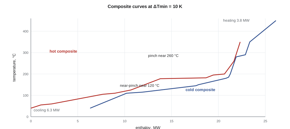
Without integration the plant would need about 19.8 MW of hot utility and 22.3 MW of cooling. With ΔTmin of 10 K, the targets fall to 3.8 MW of heating and 6.3 MW of cooling: a reduction of more than 80 % in purchased heat. The intuition was right. The pinch is at about 255 °C in shifted temperature, so all of the remaining hot utility is needed above it, at temperatures between about 255 and 450 °C, for the superheat to the first dehydration bed, the interbed reheats and the jet column reboiler. No steam the site can supply reaches that range.
The sensitivity to ΔTmin is unusual. Between 5 and 10 K the targets barely change, but at 20 K the hot utility rises to 4.6 MW and the pinch jumps to about 120 °C, where the quench condensation meets the feed vaporization. That jump says the plant has two near-pinches, and that the heat exchanged between the condensing quench gas and the boiling feed is tight. Riya keeps ΔTmin at 10 K for the high-temperature exchangers, where film coefficients of gases are poor and area is expensive, but checks that the quench-to-feed exchanger can be designed with a 10 K approach at reasonable area. Lesson 8 confirms it can, with a large plate exchanger.
Designing the heat exchanger network
Riya then designs a network that achieves close to the targets, following the pinch design rules: no heat transfer across the pinch, no hot utility below it, no cooling above it. Above the pinch, the dehydration effluent's gas cooling (350 to about 260 °C) partly superheats the feed, and the fired heater supplies the rest of the superheat and the reheats. Below the pinch, the key matches are:
- Oligomerization reactor steam to feed vaporization. The reactor raises steam at about 10 bar(g); the steam condenses in the feed vaporizer at 180 °C, boiling the hydrous ethanol and dilution water at 110 to 145 °C. This single match moves 4.6 MW and is the heart of the integration.
- Quench condensation to feed preheat and the water stripper reboiler. The bottom of the quench tower runs at about 120 °C; a pumped circuit of quench water carries heat to the feed preheater and the stripper reboiler.
- Hydrogenation product to the stabilizer and splitter reboilers, at 150 to 185 °C, and to the hydrogenation feed.
- Oligomerization loop feed-effluent exchange, as described above.
- The jet column condenser, at about 195 °C under vacuum, to the hydrogenation feed and part of the loop reheat.
What remains is cooling at low temperature: the last of the quench, the loop effluent below about 60 °C, the stabilizer condenser and the compressor intercoolers. These go to cooling water or air coolers. The network has more matches than the minimum the targets imply, because Riya splits two streams to avoid temperature crosses, and it uses about 4.0 MW of hot utility instead of the 3.8 MW target. Professor Marchetti's question is whether the last 0.2 MW is worth chasing. It is not: it would need two more exchangers to save about 50,000 dollars a year.
Steam balance
Integration creates a utility system as well as removing one. The oligomerization reactors raise about 8 t/h of 10 bar(g) steam, and the feed vaporizer condenses it. If the reactors are offline or at reduced rate, the vaporizer still needs heat. Riya therefore connects the ATJ steam system to the site's medium-pressure header in both directions: it can import steam during start-up or when oligomerization is down, and export small surpluses. The steam drum on each reactor is also the coolant system whose pressure sets the reactor's temperature, which Lesson 9 controls. A heat-integrated plant is more efficient and also more tightly coupled: an upset in one section travels to the others through the heat exchangers. Start-up needs particular thought, because the dehydration section must be running before the oligomerization reactors can make the steam that the dehydration section's feed vaporizer relies on.
The high-temperature heater
The 3.8 MW above the pinch must come from a heater. Two options are compared. A fired heater burns the plant's purge gases, about 0.6 MW of ethylene, ethane and hydrogen, together with natural gas. An electric heater uses electricity from the grid, and the purge gas goes to the site's boilers instead. The trade-off is cost against carbon, and the answer depends on the grid.
In Iowa, where the grid emits about 400 g CO₂e per kWh, the electric heater would emit about 12.4 kt CO₂e a year against 7.1 kt for the fired heater, and cost about 2 million dollars a year more. Electrification would raise both cost and emissions. The team chooses a fired heater and records that electrification would make sense only with a dedicated low-carbon supply, such as a power purchase agreement with a wind farm, which Iowa has in abundance.
The fired heater is a cylindrical vertical heater with a radiant section, where the reheat coils sit, and a convection section, where the superheat coil and an air preheater recover heat from the flue gas. Low-NOx burners keep it within the emission limits Lesson 11 will set.
Other utilities
The remaining utilities are sized from the network and the equipment list. Cooling of about 6.3 MW at a 11 K rise needs about 140 kg/s, roughly 500 m³/h, of cooling water from a new cell on the existing tower, which also loses about 2 % of its circulation to evaporation in summer. The electrical load is about 1.6 MW: the ethylene compressor, the recycle and hydrogen compressors, the vacuum system, pumps and air cooler fans. A hot oil circuit heated by the fired heater supplies the jet column reboiler. Nitrogen is needed for purging, blanketing and adsorbent regeneration, and instrument air for the control valves; both come from the site's systems. Riya lists every utility with its normal and peak demand and its cost, the data Lesson 12 needs for the operating cost.
Worked problem
Cooling water for the remaining duty
How much cooling water is needed to remove 6.3 MW with a 29 °C supply and 40 °C return, taking the heat capacity of water as 4.18 kJ/(kg·K)?
Show solution
- Mass flow \(= 6\,300 / (4.18 \times 11) = 137\) kg/s.
- At about 995 kg/m³, that is 0.138 m³/s or about 495 m³/h.
- Without integration, 22.3 MW would need about 485 kg/s, 3.5 times as much.
Answer: About 137 kg/s, close to 500 m³/h. Integration shrinks the cooling tower cell as well as the heater.
Common mistakes
MistakeDesigning exchangers before setting energy targets.
InsteadRun the problem table first; it tells you what is achievable.
MistakeTransferring heat across the pinch to use a convenient stream.
InsteadEvery unit across the pinch must be added back as both hot and cold utility.
MistakeChoosing ΔTmin by habit.
InsteadTest several values; this plant has a near-pinch that changes the targets sharply above 10 K.
MistakeAssuming electrification always lowers emissions.
InsteadCompare with the grid's emission factor; on a carbon-intensive grid it raises them.
MistakeForgetting start-up in an integrated plant.
InsteadProvide steam import and start-up heaters where one section heats another.
Summary and key terms
- Pinch analysis sets minimum utilities before any network is designed; the problem table gives them exactly.
- For the ATJ plant, integration cuts hot utility from about 19.8 to 3.8 MW and cooling from 22.3 to 6.3 MW.
- The remaining hot utility is above the pinch, at 255 to 450 °C, so it needs a heater rather than steam.
- The oligomerization reactor's steam boils the dehydration feed: the central match of the network.
- Integrated plants are coupled; steam import and start-up provisions keep them operable.
- Whether electric heating lowers emissions depends on the grid; its cost per metric ton avoided decides the choice.
- Pinch
- The temperature at which hot and cold composite curves are closest and heat cannot pass.
- Problem table algorithm
- A cascade of interval heat balances giving minimum utilities.
- ΔTmin
- The minimum temperature approach allowed between hot and cold streams.
- Composite curves
- Plots of total hot and cold stream enthalpy against temperature.
- Feed-effluent exchanger
- An exchanger heating a reactor's feed with its effluent.
- Fired heater
- A furnace heating process fluid in tubes with burning fuel.
Practice problems
Work each problem on paper first, then reveal the answer to check.
What are the minimum hot and cold utilities at ΔTmin of 10 K?
Show answer
About 3.8 MW and 6.3 MW.
Why can't plant steam supply the remaining hot utility?
Show answer
It is needed above about 255 °C, hotter than any steam the site raises.
Which match moves the most heat in the network?
Show answer
Oligomerization reactor steam to the feed vaporizer, about 4.6 MW.
Why does the pinch move when ΔTmin rises to 20 K?
Show answer
A second near-pinch, at the quench condensation and feed vaporization, becomes limiting.
What extra provision does integration need for start-up?
Show answer
Steam import, since the feed vaporizer's heat comes from the oligomerization reactors.
What decides whether an electric heater lowers emissions?
Show answer
The grid emission factor compared with that of the fuel it replaces.
Lesson quiz · 5 questions
Score 60% or more to complete this lesson.
Create a free account to save your progress, take quizzes and earn a certificate.