
BLR-130 · Lesson 8 of 12 · 20 min
Structural shapes and their layout
Boilermakers do not only build pressure parts. Every boiler, vessel and tank sits on structural steel: skirts and saddles, platforms and ladders, pipe supports, buckstays that hold boiler walls, and the steel frames of ducts and hoppers. On a boiler outage, much of the work is replacing corroded or damaged support steel, and a boilermaker must lay out and fit it from the drawings or, often, from what is left of the old piece. This lesson covers the structural shapes boilermakers use, how they are designated and measured, and how to lay out cut lengths, angle cuts, copes, bolt holes and clips.
The common shapes
Structural steel comes in a family of standard shapes. Wide-flange beams, called W shapes, have two flanges joined by a web and are the main beams and columns. Channels, called C shapes, have a web and two flanges on one side and are used for lighter beams, frames and bracing. Angles, called L shapes, have two legs at right angles and are used for bracing, clips, lintels and ladders. Hollow structural sections, or HSS, are square, rectangular or round tubes used for columns and braces. Plate, flat bar and round bar complete the set. Rails, tees cut from wide-flange beams and pipe are used too.
Designations tell the size. A wide-flange shape is designated by its nominal depth and its mass per meter or weight per foot: W12 × 40, about 12 in deep and 40 lb/ft. A channel is designated the same way, an angle by its two legs and thickness: L4 × 4 × 3/8. An HSS is designated by its outside dimensions and wall thickness. The steel tables give each shape's real depth, flange width, flange and web thicknesses, the distance called k from the outside of the flange to the end of the fillet between flange and web, and the bolt gauges, the standard distances from the back of a flange or leg to the line of holes. A layout hand uses these real dimensions, not the nominal ones.
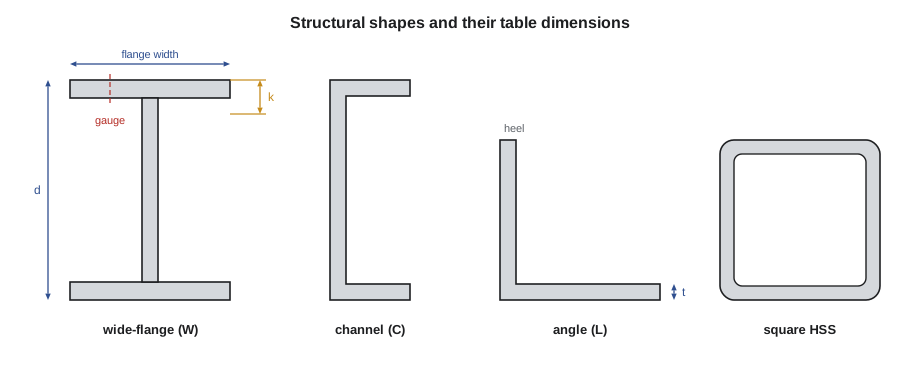
Canadian steel follows CSA G40.21, with grades such as 350W, and Canadian shapes are designated in metric; American steel follows ASTM specifications such as A992 for wide-flange shapes and A36 or A572 for other shapes and plate, designated in inches. Much of the older steel in Canadian plants is in imperial shapes, and replacement pieces may have to match them. The bill of material gives the specification and grade, and the material test report must match it.
Measuring and marking shapes
Structural shapes are not as true as they look. Rolled shapes can have flanges out of square with the web, webs off center, and sweep or camber along their length, all within the mill's tolerances. As with plate, layout on a shape starts from a reference: usually the back of a flange or the heel of an angle for lines along the piece, and a squared line across the piece near one end for lengths. Lines across a shape are squared from the reference surface with a square on each face and joined, and checked by measuring from the end along both flanges.
Wrap-around tools help. A flexible steel strip or a piece of heavy paper wrapped around a shape or pipe gives a line square to its axis; a center finder or a combination square finds the center of a web or flange. For holes in flanges, the gauge line is marked from the back of the flange and the hole centers are stepped along it. For a beam with holes in both flanges, the holes in the second flange are laid out from the first, not separately from the end, so that the two patterns match.
Cut lengths, work points and clearances
Structural drawings locate members by work points, the theoretical points where the center lines of members meet. A brace between a column and a beam runs from one work point to another, and its length on the drawing is the distance between them. The actual cut length is shorter, because the brace stops short of the column and the beam to leave room for the connection, by a clearance shown on the detail. The angle of the brace and the shape of its end cuts follow from its run and rise between the work points.
At Riverbend, the platform beside the steam drum's west end is supported by knee braces from the boiler's buckstays. The old braces are corroded through. The new detail shows each brace running between work points 48 in apart horizontally and 36 in vertically, with 1/2 in clearance at each end. The beam being coped to fit beside a column has a flange 8 in wide, a k distance of 1 1/4 in, and a 1/2 in clearance around the column flange.
# Structural layout: knee brace length and cut angle, and a beam cope (US units)
from math import sqrt, atan2, degrees, gcd
MODE = "in"

def frac(x, den=16):
    sign = "-" if x < 0 else ""
    n = round(abs(x) * den); whole, rem = divmod(n, den)
    if rem == 0:
        return f"{sign}{whole} in"
    g = gcd(rem, den)
    return f"{sign}{whole} {rem // g}/{den // g} in" if whole else f"{sign}{rem // g}/{den // g} in"

def show(x):
    return f"{x:,.0f} mm" if MODE == "mm" else frac(x)

run, rise = 48, 36          # work point to work point, horizontal and vertical
clear = 0.5                      # clearance taken off at each end
wp = sqrt(run ** 2 + rise ** 2)
ang = degrees(atan2(rise, run))
print("work point length", show(wp))
print("cut length", show(wp - 2 * clear))
print(f"brace angle {ang:.1f} deg from horizontal; end cuts at {90 - ang:.1f} deg from square")

flange, kdist, gapc = 8, 1.25, 0.5   # beam flange width of the supporting member, k distance, clearance
print("cope depth", show(kdist + gapc), "cope length", show(flange / 2 + gapc))work point length 60 in cut length 59 in brace angle 36.9 deg from horizontal; end cuts at 53.1 deg from square cope depth 1 3/4 in cope length 4 1/2 in
The work point length is 60 in, a 3-4-5 triangle scaled up, so the brace slopes at 36.9 degrees. Taking 1/2 in off each end gives a cut length of 59 in. The end cuts are made at 53.1 degrees from square, so that they sit flat against the gusset plates. The cope, the notch cut out of the beam's top flange and web end so it clears the column, is 1 3/4 in deep and 4 1/2 in long.
Copes, blocks and end cuts
When a beam frames into another beam or a column at the same level, its flange would hit the supporting member's flange. The cure is a cope: the end of the top flange and part of the web are cut away. A cope is laid out by its depth, measured down from the top of the flange, and its length, measured back from the end. Its depth is usually set by the supporting member's k distance plus a clearance, so that the coped beam clears the fillet; its length by half the supporting flange plus clearance. The inside corner of a cope must be cut with a radius, never a sharp notch, because a sharp corner starts cracks. A block is the same cut made on a flange without cutting into the web.
End cuts on braces are laid out from the angle. On an angle brace, the cut is drawn across both legs; on a channel or HSS brace, it is drawn on each face and joined. A brace that bears on a gusset plate needs its cut line to be at the right angle to the brace's axis; one that is welded around its end may be cut more simply. In the field, many fitters lay out an end cut by holding the brace in place, tacked temporarily, and scribing the cut from the member it meets. That method works only if the brace is held in its true position, which is why the work point dimensions are checked first.
Bolt holes and clips
Bolted connections use standard hole sizes, usually a little larger than the bolt, and standard gauges and spacing. Holes are laid out by their gauge from the back of the flange or leg and their pitch along it, with edge distances that must not be less than the minimums for the bolt size. Clip angles and shear tabs, which connect a beam's web to its support, are laid out as small parts and often cut in batches. On a field repair, the holes in a new clip are often match-marked from the existing holes in the old steel, using the old clip as a template or transferring the holes with a hole-center punch.
| Item | Typical layout rule | Why |
|---|---|---|
| Gauge line | Marked from the back of the flange or heel of the angle | Matches the steel table's standard gauge for the shape |
| Pitch | Hole centers stepped along the gauge line | Even spacing for the bolts and for the connection design |
| Edge distance | Not less than the minimum for the bolt size | Prevents the bolt tearing out the edge |
| Holes in both flanges | Laid out from the first flange's pattern | Keeps the patterns matched |
| Cope corner | Cut to a radius | A sharp re-entrant corner starts cracks |
Replacing steel in the field
Field replacement of structural steel adds a problem the drawing does not show: the existing steel has moved. Columns are out of plumb, beams have sagged, and the new piece must fit what is there, not what was drawn forty years ago. Before cutting the new braces for Riverbend, Dale takes Kiera up to the platform with a tape, a level and a plumb bob to measure the existing work points. The horizontal distance is 1/8 in more than the drawing, because the buckstay has bowed outward slightly. Dale's rule is to cut new steel to the drawing when the existing steel matches it within the clearances, and to field-measure and cut to fit when it does not, with the engineer's agreement. Here, the difference is less than the clearance, so the braces are cut to the drawing and fitted with the clearance taken up at one end.
Worked problem
Brace cut length
A brace runs between work points with a run of 80 in and a rise of 60 in, with 3/8 in clearance at each end. What is its cut length and angle?
Show solution
- Work point length: √(80² + 60²) = 100 in.
- Cut length: 100 − 2 × 3/8 = 99 1/4 in.
- Angle: tan⁻¹(rise / run) = tan⁻¹(0.75) = 36.9 degrees from horizontal.
Answer: Cut length 99 1/4 in at 36.9 degrees.
Templates from the old piece
On repair work, the most reliable drawing is often the old part itself. When a corroded clip or gusset is removed, a fitter traces its outline and its holes onto a sheet of template material, cardboard, thin plywood or light sheet steel, before it is scrapped, and marks the template with the part's location and orientation. Where the old part is too corroded to trace accurately, the fitter makes the template against the steel it attached to, scribing to the existing members. The template is checked against the drawing where one exists and against the field measurements, and the new part is laid out from it. Dale keeps a stack of these templates from earlier Riverbend outages in the tool crib, labeled by location, and several of the platform clips are made from them this winter.
Templates have their own errors: cardboard swells when wet, and plywood can warp. A template that will be used more than once is made of steel or aluminum sheet, and its key dimensions are written on it so that it can be checked before each use.
Shop-assembled frames
Some structural work is assembled in the shop before it goes to the field: a platform frame, a ladder with its cage, a pipe rack bent. The frame is laid out full size on the shop floor, with its work points and center lines marked on the floor or on a layout table, and the members are set to the marks, checked by diagonals, and tacked. Assembling in the shop lets the frame be checked as a whole and the connections drilled to match, so that it bolts together in the field without forcing. The Riverbend platform's new support frame is assembled this way, with Kiera checking its diagonals before Dale lets the welder start.
Common mistakes
MistakeUsing the nominal depth of a shape for layout.
InsteadUse the real dimensions from the steel tables.
MistakeCutting a brace to the work point length.
InsteadSubtract the clearances at both ends.
MistakeCutting a cope with a sharp inside corner.
InsteadCut the corner to a radius.
MistakeLaying out holes in each flange separately from the end.
InsteadLay out the second flange from the first so the patterns match.
MistakeAssuming existing field steel matches the old drawing.
InsteadField-measure work points before cutting replacement steel.
Summary and key terms
- Boilermakers use wide-flange shapes, channels, angles, HSS, plate and bar for supports and frames.
- Use the real dimensions, k distances and gauges from the steel tables, not nominal sizes.
- Members are located by work points; cut length is the work point length less end clearances.
- Brace angle and end cuts follow from the run and rise.
- Copes clear supporting flanges and must have radiused corners.
- In the field, measure what is there before cutting replacement steel.
- Work point
- The point where the center lines of connected members meet.
- Cope
- A cut removing part of a flange and web at a beam end to clear another member.
- k distance
- From the outside of a flange to the end of the fillet between flange and web.
- Gauge
- The standard distance from the back of a flange or leg to a line of holes.
- Edge distance
- The distance from a hole center to the edge of the part.
- HSS
- Hollow structural section, a square, rectangular or round steel tube.
Practice problems
Work each problem on paper first, then reveal the answer to check.
A brace has a run of 36 in and a rise of 48 in. What is the work point length?
Show answer
√(36² + 48²) = 60 in.
At what angle from horizontal does that brace slope?
Show answer
tan⁻¹(48/36) = 53.1 degrees.
Why is a cope's inside corner radiused?
Show answer
A sharp re-entrant corner concentrates stress and starts cracks.
What does W12 × 40 mean?
Show answer
A wide-flange shape about 12 in deep, 40 lb per foot.
Lesson quiz · 5 questions
Score 60% or more to complete this lesson.
Create a free account to save your progress, take quizzes and earn a certificate.