
BLR-130 · Lesson 3 of 12 · 20 min
Weld symbols and bills of material for fitters
A fitter does not make the weld, but the fitter decides whether the welder can make it. The joint preparation, the root opening, the alignment and the position of every piece are set at fit-up, and all of them are specified on the drawing by the weld symbol and the bill of material. A fitter who misreads a weld symbol can fit a joint with the bevel on the wrong side, the gap too tight for full penetration, or a fillet weld where a groove weld was needed. This lesson covers how weld symbols are built and read, what they tell the fitter in particular, and how the bill of material and cut list connect the drawing to the steel on the floor.
Weld symbols and welding symbols
Two terms are easy to confuse. A weld symbol is the small graphic that shows the type of weld: a triangle for a fillet, a V for a V-groove, a bevel line for a bevel groove, and so on. A welding symbol is the whole assembly that tells everything about the weld: a reference line, an arrow pointing to the joint, the weld symbol on the reference line, dimensions, supplementary symbols, and sometimes a tail with a process or procedure reference. North American shops use the symbol system of AWS A2.4, the American Welding Society's standard for welding and inspection symbols, now in its 2020 edition. Canadian drawings use the same system, and CSA W59 and the boilermaker trade's training materials teach it the same way.
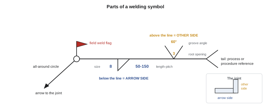
Arrow side and other side
The most important rule in reading a welding symbol is where the weld symbol sits on the reference line. A weld symbol below the line applies to the arrow side of the joint, the side the arrow touches. A weld symbol above the line applies to the other side, the far side of the joint from the arrow. Symbols on both sides mean welds on both sides. The rule holds whichever way the arrow points and whichever end of the reference line it is on.
For a fitter, the arrow has a second meaning on bevel and J-groove welds. When only one of the two members is prepared, the arrow points with a break, a bend in the arrow line, toward the member that gets the bevel. A fitter who bevels the wrong plate has made a joint that cannot be welded as drawn, and on thick plate the mistake can cost a new plate.
Dimensions on the symbol
Each part of the symbol has a place. For a fillet weld, the size of the leg goes to the left of the triangle. For a groove weld, the depth of preparation and the weld size, in brackets, go to the left of the groove symbol, and the root opening goes inside the symbol, with the groove angle just outside it. The length of a weld, if it is not continuous, goes to the right of the symbol, and for an intermittent weld the pitch, the distance from center to center of the segments, follows the length after a dash. A circle at the junction of the arrow and the reference line means the weld goes all the way around the joint. A flag at the same point means a field weld, made at the site rather than in the shop. The tail, if there is one, holds a reference to a welding procedure, a process, or another note.
| Item | Where it goes | What the fitter does with it |
|---|---|---|
| Fillet size | Left of the fillet symbol | Leaves enough access and checks fit-up gap is small enough |
| Groove angle | Outside the groove symbol | Bevels or checks the bevel to give this included angle |
| Root opening | Inside the groove symbol | Sets the gap with spacers or a gauge before tacking |
| Depth of preparation and weld size | Left of the groove symbol, size in brackets | Sets the root face and depth of bevel |
| Length and pitch | Right of the symbol | Marks where intermittent welds start and stop |
| All around | Circle at the arrow junction | Fits the joint for welding all the way around |
| Field weld | Flag at the arrow junction | Leaves the joint unwelded in the shop, often tacked or bolted for shipping |
Supplementary symbols add more: a backing bar or backing strip symbol, a spacer, a melt-through requirement, a flush or convex contour, and a finish method. Nondestructive examination symbols use the same reference line with letters, such as RT for radiography and UT for ultrasonic testing. A fitter who sees a backing symbol must fit the backing strip before tacking, because it cannot be added afterwards.
Reading the symbols on V-412
Kiera works through the welding symbols on the V-412 skirt and base ring detail. Joanne has her write each one out in words before fitting anything, so that she reads the symbol and does not guess. Kiera writes a short script for the practice, reading each symbol from its parts the way the drawing gives them, and then totals the bill of material for the drum.
# Reading a weld symbol and totalling a bill of material (US units)
def read_symbol(side, weld, size, length=None, pitch=None, all_around=False, field=False):
    where = {"arrow": "on the arrow side of the joint", "other": "on the other side of the joint",
             "both": "on both sides of the joint"}[side]
    text = f"{weld} weld, {size}, {where}"
    if length and pitch:
        text += f", intermittent: {length} long at a pitch of {pitch}"
    if all_around:
        text += ", all around"
    if field:
        text += ", made in the field, not in the shop"
    return text

symbols = [("arrow", "fillet", "5/16 in", None, None, {}),
           ("both", "single-V groove", "5/8 in, 60 deg included, 1/8 in root opening", None, None, {}),
           ("other", "fillet", "1/4 in", "2 in", "6 in", {}),
           ("arrow", "fillet", "3/8 in", None, None, {"all_around": True, "field": True})]
for s in symbols:
    print("-", read_symbol(*s[:5], **s[5]))

bom = [("S1", "shell plate 5/8 in", 3, 4_084),
       ("H1", "2:1 elliptical head 5/8 in", 2, 1_200),
       ("BR1", "base ring 1 in", 1, 731),
       ("N1", "nozzle neck and flange", 4, 135)]          # mark, description, quantity per drum, weight each (lb)
drums = 1
print(f"\nbill of material for {drums} drum(s)")
grand = 0
for mark, desc, qty, w in bom:
    n = qty * drums
    grand += n * w
    print(f"{mark:<5}{desc:<32}{n:>4} x {w:>7,.0f} = {n * w:>8,.0f} lb")
print(f"total {grand:,.0f} lb")- fillet weld, 5/16 in, on the arrow side of the joint - single-V groove weld, 5/8 in, 60 deg included, 1/8 in root opening, on both sides of the joint - fillet weld, 1/4 in, on the other side of the joint, intermittent: 2 in long at a pitch of 6 in - fillet weld, 3/8 in, on the arrow side of the joint, all around, made in the field, not in the shop bill of material for 1 drum(s) S1 shell plate 5/8 in 3 x 4,084 = 12,252 lb H1 2:1 elliptical head 5/8 in 2 x 1,200 = 2,400 lb BR1 base ring 1 in 1 x 731 = 731 lb N1 nozzle neck and flange 4 x 135 = 540 lb total 15,923 lb
The first symbol is a single fillet on the arrow side. The second is a double-sided V-groove with a root opening the fitter must hold; on the drum's long seams, the drawing calls for full penetration welded from both sides, so the welder back-gouges the root after the first side. The third is an intermittent fillet on the other side, used for the stiffening clips on the skirt opening. The fourth is a field fillet all around, for a clip that is welded at the site after the vessel is set.
The bill of material
The bill of material lists every part needed to build the piece, with its mark, a description, the quantity, the material specification and the size. On a vessel, it also lists the material's specification and grade, which decides the welding procedure and the filler metal. On structural steel, the bill lists each shape by its designation and length. The bill is where the shop's purchasing, cutting and fitting meet: purchasing orders from it, the detailer nests from it, and the fitter checks every piece against it before fitting.
The mark on each part is the key. It appears on the bill, on the drawing, on the cut sheet, and painted or stamped on the piece itself. When a fitter picks up a piece marked SK1 from the rack, the mark tells him which drawing it belongs to and where it goes. A piece with no mark is a piece that has to be measured and identified before it can be used, and on pressure work it may not be usable at all.
The bill also feeds the weight estimates used for rigging and shipping. In the script above, the bill's weights add up to the drum's steel weight before the internals and the weld metal are added. The finished base ring is much lighter than the blank it is cut from, because the center of the blank is cut out; the bill lists the finished part, and the cut list, which follows, lists the blank.
Cut lists and nesting
A cut list translates the bill of material into the pieces to be cut, with their cut sizes. Cut sizes are not always the finished sizes. A plate to be rolled into a shell is cut to the mean circumference less the root opening, with an allowance for weld shrinkage, as lesson 7 shows. A plate to be beveled may be cut oversize to allow for the bevel. A plate that will be trimmed after rolling may be cut with extra length. A structural member may be cut with an allowance for fitting in the field. The cut list states each allowance so that nobody takes it off a second time.
Nesting arranges the pieces on the available plates to use as much of the plate as possible. A good nest keeps the plate's rolling direction where the drawing requires it, keeps pieces that must be traced to the same heat on the same plate, leaves room for the cutting kerf between pieces, and leaves usable offcuts rather than slivers. On V-412, each shell plate is cut from a single plate as bought, and the offcut strip along one end goes into the shop's stock for reinforcing pads and clips, each piece taking the heat number of its parent plate.
Worked problem
Reading a groove weld symbol
A welding symbol has a V-groove symbol on both sides of the reference line, with 60° outside the symbol and 1/8 in inside it. What does the fitter set up?
Show solution
- Symbols on both sides mean the joint is welded from both sides.
- The 60° is the included groove angle, so each plate edge is beveled 30 degrees.
- The 1/8 in inside the symbol is the root opening.
- The fitter bevels both plates, sets the gap with spacers and tacks the joint.
Answer: A double-welded single-V joint, 60° included, with a 1/8 in root opening.
When the symbol and the procedure disagree
Sometimes the welding symbol on the drawing and the welding procedure specification for the joint do not agree: the drawing shows a 60-degree groove and the procedure allows 45 to 60, or the drawing shows a root opening the procedure does not cover. The procedure is what the welder is qualified to and what the inspector will check against, so a fitter who sees a disagreement does not pick one; he raises it. On V-412, the shop's engineering office checks every welding symbol against the procedure before the drawings are released, but the fitter is the last person who can catch an error before the steel is prepared, and Joanne expects her fitters to look.
A fitter also needs to know which joints will be examined, and how. A joint marked for radiography will be judged on its root and its fusion, and the fitter's root opening and alignment decide both. A joint marked for ultrasonic testing may need its surfaces ground flush for the probe. The examination symbols on the drawing and the inspection plan tell which is which.
Common mistakes
MistakeReading the symbol's position by the direction of the arrow.
InsteadBelow the line is always the arrow side; above is always the other side.
MistakeBeveling the wrong member of a bevel-groove joint.
InsteadBevel the member the broken arrow points to.
MistakeTacking before fitting the backing strip.
InsteadFit the backing called for by the symbol before any tack is made.
MistakeWelding a field weld in the shop.
InsteadLeave field welds for the site, as the flag shows.
MistakeTaking an allowance off a cut size twice.
InsteadCheck whether the cut list size already includes the allowance.
Summary and key terms
- A welding symbol has a reference line, an arrow, weld symbols, dimensions and an optional tail; North American drawings follow AWS A2.4.
- Below the line is the arrow side; above the line is the other side.
- A broken arrow on a bevel or J-groove points to the member that is prepared.
- Groove angle, root opening and depth of preparation tell the fitter how to prepare and gap the joint.
- The all-around circle and field-weld flag sit at the junction of arrow and reference line.
- The bill of material and cut list connect the drawing to the pieces; marks keep every piece identified.
- Welding symbol
- The full assembly of reference line, arrow, weld symbol and dimensions.
- Weld symbol
- The graphic showing the type of weld, such as a fillet or a groove.
- Arrow side
- The side of the joint the arrow touches; symbols below the line apply to it.
- Root opening
- The gap between members at the root of a groove weld.
- Pitch
- The center-to-center spacing of intermittent weld segments.
- Cut list
- The list of pieces to be cut, with cut sizes and allowances.
Practice problems
Work each problem on paper first, then reveal the answer to check.
A fillet symbol sits above the reference line. Which side is welded?
Show answer
The other side, away from the arrow.
What does a flag at the arrow junction mean?
Show answer
A field weld, made at the site.
An intermittent fillet reads 1/4 2-6. What do the numbers mean?
Show answer
A 1/4 in fillet, segments 2 in long, at 6 in pitch.
Why are cut sizes not always finished sizes?
Show answer
They include allowances for rolling, beveling, shrinkage or trimming.
Lesson quiz · 5 questions
Score 60% or more to complete this lesson.
Create a free account to save your progress, take quizzes and earn a certificate.