
AUTO-130 · Lesson 10 of 12 · 22 min
Anti-lock brakes, traction control and stability control
In the first week of December, van 3 of Hal Osei's fleet comes in with three amber lamps lit on its dash: the anti-lock brake lamp, the traction control lamp and the stability control lamp. The driver says the lamps came on after a cold night, went off, came back, and are now on all the time, and that the van slid a little at a stop sign on packed snow, with no pulsing in the pedal. Marty plugs in the scan tool and hands Kiran the tablet. “The service brakes still work, but the van has lost all its electronic help, in December. Let's find out why.”
This lesson explains why wheels lock, what anti-lock brakes do about it, and how the system's sensors, valves, pump and module work. It then explains how the same hardware provides electronic brake force distribution, traction control and electronic stability control, introduces automatic emergency braking, and shows how to diagnose a typical fault: a wheel speed sensor.
Slip and why locked wheels are a problem
A rolling tire that is braking turns slightly slower than the road speed beneath it. The difference, expressed as a percentage of the vehicle's speed, is called slip. A freely rolling wheel has zero slip; a locked, skidding wheel has 100 percent. As braking force rises, slip rises too, and the tire's grip, its coefficient of friction, rises with it, up to a peak at roughly 10 to 20 percent slip on most surfaces. Beyond that peak, grip falls, and a fully locked tire has noticeably less grip than one at the peak, especially on wet roads. Just as important, a locked tire has almost no sideways grip, so it cannot steer: a car with locked front wheels goes straight on wherever the steering wheel is pointed, and one with locked rear wheels tends to spin.
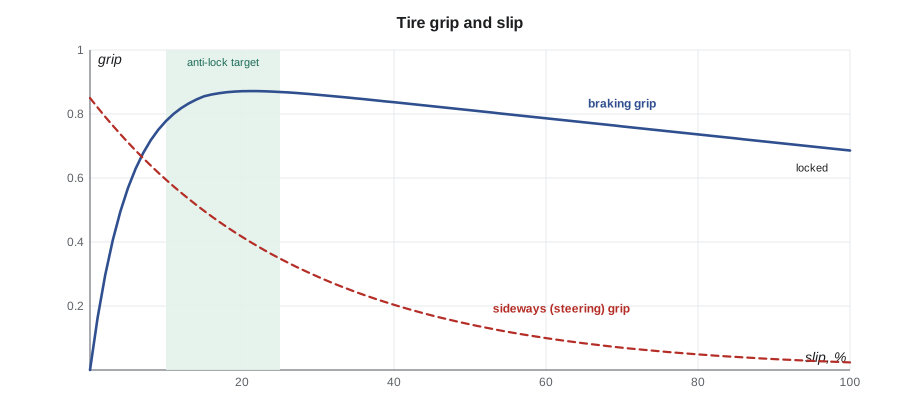
Anti-lock brakes keep each wheel in the band of slip where grip is greatest and the tire can still steer. On most surfaces that gives a shorter stop than a locked skid, and on every surface it lets the driver steer around an obstacle while braking hard. On loose gravel and deep fresh snow, a locked tire can sometimes stop shorter, because it builds a wedge of material in front of it, but it still cannot steer; anti-lock systems are tuned for these surfaces too.
# Wheel slip from the four wheel speed sensors during a hard stop (readings from a scan tool recording)
UNITS = "US"
vehicle_speed = 37.3                          # mph, estimated by the module from the wheels
wheels = {"left front": 31.3, "right front": 32.1, "left rear": 25.5, "right rear": 34.2}
for name, w in wheels.items():
    slip = (vehicle_speed - w) / vehicle_speed * 100
    action = "reduce pressure" if slip > 25 else ("hold pressure" if slip > 15 else "allow pressure to build")
print(f"{name:<12} {w:5.1f} mph slip {slip:5.1f} % -> {action}")left front 31.3 mph slip 16.1 % -> hold pressure right front 32.1 mph slip 13.9 % -> allow pressure to build left rear 25.5 mph slip 31.6 % -> reduce pressure right rear 34.2 mph slip 8.3 % -> allow pressure to build
The thresholds in the code are illustrative; real systems use more complex logic that also watches each wheel's deceleration. But the idea is the same: each wheel is controlled separately, and a wheel that starts to slow faster than the vehicle has its pressure reduced before it locks.
The parts of an anti-lock system
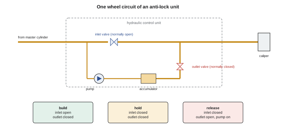
Every anti-lock system has the same main parts. A wheel speed sensor at each wheel, or on older trucks one sensor in the rear axle, measures how fast the wheel turns. A hydraulic control unit, also called the modulator, sits between the master cylinder and the wheels and contains a pair of solenoid valves for each wheel circuit, a small pump and motor, and low-pressure accumulators. An electronic control module, usually mounted on the hydraulic unit, reads the sensors, decides what each wheel needs, and controls the valves and pump. The red brake lamp warns of hydraulic and parking brake problems; an amber anti-lock lamp warns that the anti-lock system has a fault and has switched itself off, leaving normal braking without anti-lock control.
Each wheel circuit has an inlet valve, open when not powered, which lets master cylinder pressure through to the wheel, and an outlet valve, closed when not powered, which can release fluid from the wheel into an accumulator. During normal braking, both valves are unpowered, and the system is simply part of the hydraulic line. When a wheel starts to lock, the module closes that wheel's inlet valve to hold the pressure steady. If the wheel still slows too fast, it opens the outlet valve to release some pressure into the accumulator, and the pump returns that fluid to the master cylinder circuit. When the wheel speeds up again, the module closes the outlet and reopens the inlet to build pressure. This build, hold and release cycle can run many times a second at each wheel, and the pump's pulses pushing fluid back into the master cylinder are what the driver feels as a buzzing, pulsing pedal. That pulsing is normal, and drivers are taught to keep pressing firmly through it rather than pumping the pedal.
Wheel speed sensors
There are two kinds of wheel speed sensor. A passive sensor, used on older vehicles, is a coil wound around a magnet, mounted close to a toothed tone ring that turns with the wheel. As each tooth passes, it changes the magnetic field and induces a small alternating voltage in the coil. The voltage's frequency shows the wheel's speed, and its size rises with speed, so at very low speeds the signal is weak. A passive sensor has two wires and a measurable coil resistance, typically from several hundred to a couple of thousand ohms.
An active sensor, used on nearly all modern vehicles including Hal's vans, contains electronics, a Hall-effect or magnetoresistive element, and is powered by the module. It reads either a steel tone ring or, more often, a magnetic encoder ring built into the wheel bearing's seal, with alternating north and south poles. It sends a square-wave signal, often as a switching current between two levels, whose frequency shows the speed, and it works down to almost zero speed. Some active sensors also tell the module the direction of rotation. An active sensor cannot be tested with an ohmmeter; it is tested by its signal, on a scan tool or with a lab scope, and by its supply.
# Expected wheel speed sensor signal frequency at a given road speed
import math
UNITS = "US"
tire_diameter_m = 0.74                 # van tire, loaded
poles = 48                             # magnetic pole pairs (or teeth) per revolution
for spd in (3, 20, 60):
    v = spd / 3.6 if UNITS == "metric" else spd * 0.44704      # m/s
    rev_per_s = v / (math.pi * tire_diameter_m)
    freq = rev_per_s * poles
print(f"{spd:3d} mph: wheel {rev_per_s * 60:5.0f} rpm, sensor signal about {freq:5.0f} Hz")3 mph: wheel 35 rpm, sensor signal about 28 Hz 20 mph: wheel 231 rpm, sensor signal about 185 Hz 60 mph: wheel 692 rpm, sensor signal about 554 Hz
Diagnosing van 3
The scan tool shows a stored code for the right rear wheel speed sensor: signal erratic or missing. Kiran records the freeze frame data, which shows the fault first set at 0 °F with the van moving slowly. She clears nothing yet. Marty's rule is to see the fault before replacing anything, so with Theo driving the van slowly around the empty back lot she watches the four wheel speeds on the scan tool's live data. The fronts and left rear track together. The right rear reads normally at times and then drops to zero for a moment, especially over bumps.
On the lift, Kiran inspects the sensor and its wiring first, because most wheel speed sensor faults are wiring faults. The harness is clipped properly and undamaged, and the connector is dry. She removes the sensor: its tip is covered in rust flakes, and when she shines a light into the hub bore she can see that rust has grown on the bearing housing and pushed the sensor slightly outward in its bore, so that the gap to the encoder ring has grown. This is common in salt climates and is sometimes called rust jacking. The sensor itself checks out when tested with a lab scope while she spins the wheel by hand: the signal is a clean square wave once the sensor is held at the correct gap.
# Van 3, right rear: scan tool wheel speeds at a steady slow speed (illustrative recording)
UNITS = "US"
samples = [(11.3, 11.2), (11.4, 0.0), (11.6, 11.5), (11.4, 0.0), (11.2, 11.2)]       # (left rear, right rear) in mph
for lr, rr in samples:
    diff = abs(lr - rr)
    flag = "  <- signal lost" if rr == 0 else ("  <- mismatch" if diff > 1.2 else "")
    print(f"left rear {lr:5.1f}  right rear {rr:5.1f} mph{flag}")
lost = sum(1 for _, rr in samples if rr == 0)
print(f"{lost} of {len(samples)} samples lost: intermittent signal, check the gap, mounting and wiring before the sensor")left rear 11.3 right rear 11.2 mph left rear 11.4 right rear 0.0 mph <- signal lost left rear 11.6 right rear 11.5 mph left rear 11.4 right rear 0.0 mph <- signal lost left rear 11.2 right rear 11.2 mph 2 of 5 samples lost: intermittent signal, check the gap, mounting and wiring before the sensor
The repair is to clean the sensor bore and its mounting face of rust down to bare metal, without damaging the encoder ring inside, coat the bore lightly with the corrosion-inhibiting grease or compound the manufacturer specifies, and fit a new sensor, because the old one's tip is pitted. Kiran then clears the code, road tests the van, watches the four speeds match on live data, and makes a controlled hard stop on the snowy back lot to feel the anti-lock system work, with the pedal pulsing and the van straight. The lamps stay off. She notes on the repair order that the other three sensors' bores show early rust and should be checked at the van's next brake service.
Electronic brake force distribution and traction control
The same valves and sensors do several other jobs. Electronic brake force distribution, mentioned in Lessons 2 and 3, compares rear wheel slip with front wheel slip during ordinary braking, long before the anti-lock threshold, and uses the rear inlet valves to limit rear pressure when the rears start to slip more than the fronts. It replaces the proportioning valve and adapts automatically to load.
Traction control works in the opposite direction, during acceleration. When a drive wheel spins faster than the others, for example on ice at a green light, the module can apply that wheel's brake, using the pump and extra valves called isolation and priming valves that let it build pressure without the driver touching the pedal. Braking the spinning wheel sends the torque, through the differential, to the wheel that has grip. If both drive wheels spin, the module also asks the engine control module to cut engine torque. On electric and hybrid vehicles, it can cut motor torque almost instantly.
Electronic stability control
Electronic stability control, often called ESC, uses the anti-lock and traction control hardware plus three more sensors: a steering angle sensor that tells it where the driver wants to go, and a yaw rate sensor and a lateral acceleration sensor, usually in one unit near the vehicle's middle, that tell it where the vehicle is actually going. When the two disagree, the module brakes individual wheels to turn the vehicle back onto the driver's intended path. In understeer, when the front slides wide and the vehicle turns less than the driver asks, it mainly brakes the inside rear wheel to pull the nose into the turn. In oversteer, when the rear slides out and the vehicle turns more than asked, it mainly brakes the outside front wheel to straighten it. It can also reduce engine torque.
Stability control has been one of the most effective safety technologies ever fitted to vehicles, particularly in preventing rollovers of tall vehicles like vans and pickups. It has been required on all new light vehicles in the United States since the 2012 model year, under FMVSS 126, and in many other countries. Because it depends on accurate sensor readings, a steering angle sensor often needs a calibration, or zero-point learn, with a scan tool after a wheel alignment, a steering repair or a module replacement; otherwise the system may intervene when it should not, or set a fault.
# Stability control: compare the yaw rate the driver asks for with the yaw rate measured
UNITS = "US"
def intended_yaw(speed_ms, steer_deg, ratio=16.0, wheelbase=3.75, k_us=0.004):
    road_wheel = steer_deg / ratio * 3.1416 / 180
    return speed_ms * road_wheel / (wheelbase * (1 + k_us * speed_ms ** 2)) * 180 / 3.1416      # degrees per second
cases = [("gentle curve, dry", 22.0, 30, 3.8), ("icy curve, front sliding", 15.0, 90, 5.0), ("icy curve, rear sliding", 15.0, 45, 14.5)]
for name, v, steer, measured in cases:
    want = intended_yaw(v, steer)
    if measured < 0.8 * want:
        act = "understeer: brake the inside rear, cut torque"
    elif measured > 1.2 * want:
        act = "oversteer: brake the outside front"
    else:
        act = "no intervention"
    spd = f"{v * 3.6:3.0f} km/h" if UNITS == "metric" else f"{v * 2.237:3.0f} mph"
print(f"{name:<26} {spd}: wanted {want:4.1f} deg/s, measured {measured:4.1f} -> {act}")gentle curve, dry 49 mph: wanted 3.7 deg/s, measured 3.8 -> no intervention icy curve, front sliding 34 mph: wanted 11.8 deg/s, measured 5.0 -> understeer: brake the inside rear, cut torque icy curve, rear sliding 34 mph: wanted 5.9 deg/s, measured 14.5 -> oversteer: brake the outside front
Automatic emergency braking
Many newer vehicles add automatic emergency braking, which uses forward-looking cameras and radar to detect a vehicle or pedestrian ahead and, if the driver does not react to a warning, applies the brakes on its own through the stability control hydraulics or an integrated electric brake system. A federal rule, FMVSS 127, issued in 2024, requires it on new light vehicles from September 2029, and NHTSA has declined industry requests to delay that date. The sensors, their calibration after repairs, and the other driver assistance systems are the subject of AUTO-420; in this course, the point is that automatic emergency braking depends on a healthy brake system, and that a brake fault can disable it.
Worked problem
Why did all three lamps come on for one sensor?
Hal asks why a single sensor turned off the anti-lock, traction and stability control, and why the van still stopped.
Show solution
- The anti-lock module needs a reliable speed from every wheel to decide how much each one is slipping.
- With the right rear signal dropping out, the module could not trust its calculations, so it switched off anti-lock control and every function that depends on it: traction control and stability control.
- The hydraulic brakes are not affected: the valves rest open to the wheels, so the van stops normally, but without anti-lock control a hard stop on snow can lock the wheels, which is what the driver felt.
- Rust had pushed the sensor away from its encoder; the bore was cleaned and protected and a new sensor fitted, and all three systems are working again.
Answer: All three functions depend on the wheel speed sensors; the van kept its normal brakes but lost its electronic help until the sensor was fixed.
Common mistakes
MistakeReplacing a wheel speed sensor because a code names it.
InsteadWatch live data, inspect the wiring, gap and mounting, and check the signal first.
MistakeTesting an active sensor with an ohmmeter.
InsteadTest it by its signal and its supply.
MistakeTelling drivers to pump the pedal when anti-lock activates.
InsteadPress firmly through the pulsing and steer.
MistakeForgetting the steering angle calibration after an alignment.
InsteadDo the zero-point learn the procedure requires.
MistakeAssuming an amber anti-lock lamp means no brakes.
InsteadNormal braking remains, but anti-lock and stability help are off.
Summary and key terms
- Grip peaks at about 10 to 20 percent slip, and a locked wheel cannot steer.
- Anti-lock brakes cycle inlet and outlet valves at each wheel to hold slip near the peak; the pedal pulses as they work.
- Passive sensors make an alternating voltage; active sensors send a powered square-wave signal down to near zero speed.
- Most sensor faults come from wiring, mounting, gap or rust, and are confirmed on live data.
- The same hardware provides brake force distribution, traction control and stability control.
- Stability control brakes single wheels to correct understeer and oversteer and needs calibrated sensors.
- Slip
- The difference between vehicle speed and wheel speed, as a percentage of vehicle speed.
- Hydraulic control unit
- The anti-lock valve block with inlet and outlet valves, pump and accumulators.
- Active wheel speed sensor
- A powered sensor that sends a square-wave signal from a tone ring or encoder.
- Encoder ring
- A magnetic ring with alternating poles, often in the wheel bearing seal, read by an active sensor.
- Traction control
- A function that limits drive wheel spin by braking the wheel and reducing torque.
- Electronic stability control
- A function that brakes individual wheels to keep the vehicle on the intended path.
- Yaw rate
- How fast the vehicle is rotating about its vertical axis.
Practice problems
Work each problem on paper first, then reveal the answer to check.
At 40 mph, a wheel turns at a speed equal to 32 mph. What is its slip?
Show answer
(40 − 32) / 40 × 100 = 20 percent.
What does the driver feel when anti-lock brakes are working, and what should they do?
Show answer
A pulsing pedal; keep pressing firmly and steer.
Why can't an active wheel speed sensor be tested with an ohmmeter?
Show answer
It contains electronics; it is tested by its powered signal.
In oversteer, which wheel does stability control usually brake?
Show answer
The outside front wheel.
Lesson quiz · 5 questions
Score 60% or more to complete this lesson.
Create a free account to save your progress, take quizzes and earn a certificate.