
TRD-105 · Lesson 5 of 12 · 22 min
Rigging hardware: shackles, hooks, eyebolts and spreader bars
Slings rarely work alone. They are joined to loads and hooks by hardware: shackles that connect sling eyes to lugs, hooks with safety latches, eyebolts screwed into equipment, master links that gather several legs, and spreader bars that hold slings apart. Each piece has its own rated capacity, its own rules for how it may be loaded, and its own ways of failing. A rig is only as strong as its weakest part, and the weakest part is often a small piece of hardware that was loaded the wrong way.
On Kingsway Tower the rooftop make-up air unit for the residential corridors arrived with four lifting lugs welded to its base frame and a manufacturer's drawing showing a spreader bar arrangement. Hector Ruiz walked Maya and Sam through the rig the day before the lift: shackles on each lug, sling legs up to a spreader bar, two more legs from the bar to the crane hook. "Every piece in this rig has a tag or a stamp," he said. "If I can't read it, it doesn't go on the hook."
Hardware must be rated and identified
Rigging hardware used for lifting must be made for lifting, rated by its manufacturer and permanently marked. A shackle, for example, is normally forged with the manufacturer's name or mark, its size and its working load limit, and many are also marked with a grade or traceability code. Hardware from a farm supply or hardware store that is not rated for overhead lifting, such as a cast hook or an unmarked shackle, has no place in a lifting rig. Hardware standards such as ASME B30.26 for shackles, eyebolts, links and turnbuckles, and ASME B30.10 for hooks, set the marking, inspection and removal rules that most North American manufacturers follow.
As with slings, the working load limit is the breaking strength divided by a design factor, commonly 5 to 1 or 6 to 1 for hardware. And as with slings, that margin is not available for you to use.
Shackles
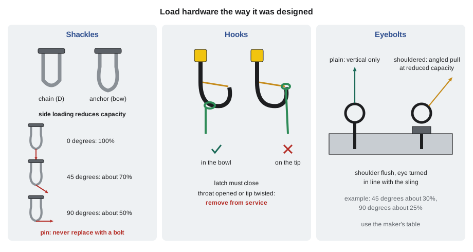
Shackles are U-shaped connectors closed by a pin. The two shapes are the chain or D shackle, with straight sides, which is designed for an in-line pull, and the anchor or bow shackle, with a rounder body that accepts slings or loads from a range of directions. The two common pins are:
- Screw pin: the pin threads into one ear of the shackle. Quick to use, but the pin can unscrew if the shackle rotates, for example when a sling runs over it. Screw pins must be fully seated, with the collar against the ear, and on long-term or rotating connections are moused (secured with wire) so they cannot back out.
- Bolt type: a bolt with a nut and a cotter pin. More secure for permanent or long-term rigging and for connections where the pin might rotate. The cotter pin must always be installed.
Rules for shackles that Hector drills into every apprentice:
- Never replace a shackle pin with a bolt. A bolt is not made of the same steel and will not have the same strength. Use only the manufacturer's matching pin.
- Load the shackle in line with its body, along its centreline. Side loading, where the force pulls across the shackle at an angle, reduces its capacity. Manufacturers publish reduction tables; a common pattern is about 70 percent of the rated load at 45 degrees and about 50 percent at 90 degrees. Some shackles may not be side loaded at all.
- Centre the load on the pin and bow. Spacers can be used to keep a narrow lug or sling centred on a wide pin. Never pack the pin with washers that let the load sit off-centre.
- When a shackle is used in a choker hitch, keep the running part of the sling against the bow, not the pin. A sling sliding over the pin can turn it and unscrew it.
- When a shackle connects two sling legs on a hook, put the legs on the bow and the pin on the hook, so the legs do not spread the shackle.
Hooks
Crane hooks, hoist hooks and sling hooks are forged, rated and marked. Most hooks used in construction have a spring-loaded safety latch that closes the throat so a sling cannot jump out if the load goes slack. The latch is not a load-bearing part: it only keeps the sling in place. Rules for hooks:
- Seat the load in the bowl, the bottom of the hook, never on the tip. A tip load acts on a long lever and can bend or break the hook at a fraction of its rated load.
- Make sure the latch closes completely. A latch that is bent, missing or held open must be repaired or the hook removed from service, unless the site allows a specific latch-less hook for a specific purpose with special precautions.
- Do not overcrowd a hook. Too many sling eyes on one hook can force the latch open or load the tip. Use a shackle or master link to gather several legs.
- Watch for opening and twisting. A hook whose throat has opened, usually judged against the original opening or marks stamped by the manufacturer, or whose tip has twisted out of the plane of the body, has been overloaded and must be removed from service. The hook standard and the manufacturer give the limits, often around 5 percent of throat opening and 10 degrees of twist.
Many crane hooks swivel so the load can rotate without twisting the hoist rope. On a crane hook, the rigger does not adjust or repair anything; any concern goes to the operator and the lift director.
Eyebolts and hoist rings
Eyebolts screw into threaded holes in equipment so the equipment can be lifted. They come in two main forms, and the difference matters:
- Plain shank eyebolts have no shoulder. They may be used only for a vertical pull in line with the bolt. Any angle bends the shank and can snap it.
- Shouldered eyebolts have a collar that bears against the surface of the equipment. They can take an angled pull in the plane of the eye, but only at a reduced capacity, and only when the shoulder is fully seated flat against the surface. Manufacturer tables commonly drop the capacity to about a third or less at 45 degrees and to about a quarter at 90 degrees.
Two more rules: the eye must be turned so the sling pulls in the plane of the eye, never across it (use shims or washers only as the manufacturer allows to align it), and the bolt must engage enough thread. A common guideline is thread engagement of at least one and a half times the bolt diameter in steel, more in softer metals, but the equipment maker's instructions govern. Never use an eyebolt that is bent, has damaged threads or will not seat.
Where a lift needs angled pulls on a threaded point, a swivel hoist ring is usually better than an eyebolt. Hoist rings pivot and swivel to line up with the sling and are rated for angled loads, but they must be torqued to the manufacturer's value and inspected like any other hardware.
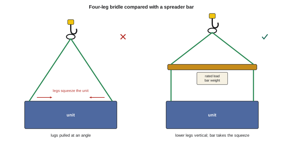
Equipment lifting lugs are another matter: they are designed by the equipment manufacturer for a particular lift arrangement, often vertical or within a stated angle. The make-up air unit's drawing called for a spreader bar precisely because its lugs were designed for vertical pulls. Following the drawing is part of the rigging.
Master links, rings and turnbuckles
Master links gather two or more sling legs onto a single hook. They are sized so the hook can seat the link in its bowl and the legs can hang without crowding. Sub-assemblies of master links let four-leg slings sit correctly. Turnbuckles adjust the length of a rigging line or a tie and must be locked with lock nuts or wire so they cannot turn under vibration; they are loaded only in straight tension. Wire rope clips, used for some terminations and guy lines, must be the right size, the right number and installed with the saddle on the live (load-bearing) part of the rope. The old saying is "never saddle a dead horse": the U-bolt goes on the dead end, the saddle on the live end. Clipped terminations are not used for general slings.
Spreader bars and lifting beams
A spreader bar is a rigid bar or tube that holds sling legs apart. Legs run from the crane hook down to each end of the bar, and more legs run from the bar down to the load. The bar takes the inward squeeze that angled slings would otherwise put on the load, and lets the lower legs hang vertically onto lugs that were designed for vertical pulls. In a true spreader bar, the bar is mostly in compression.
A lifting beam is similar but hangs from the hook at one or two points and carries the load in bending, with the load attached below. Lifting beams can reduce headroom, because there are no upper sling legs, and are used where height is limited.
Both are below-the-hook lifting devices. They must be designed for lifting (typically by an engineer to a below-the-hook design standard), marked with their rated capacity and their own weight, and inspected like other rigging. A length of pipe or a scrap beam picked up from the yard is not a spreader bar. Remember too that the weight of the bar and its rigging is part of the load on the crane.
Worked example: checking hardware in the make-up air unit rig
Worked problem
Shackles and the spreader bar
The make-up air unit weighs 2,950 kg. It hangs from four vertical legs below a spreader bar, each shackled to a lug. The upper legs run from the bar to the hook at 60 degrees from horizontal. The bar weighs 180 kg. Assuming two of the four lower legs could carry the load if the unit rocks, what working load limit is needed for each lower shackle, and what tension is in each upper leg?
Show solution
- Lower legs hang vertically, so no angle factor. If two legs carry the load: 2,950 / 2 = 1,475 kg per shackle.
- Choose shackles with a working load limit of at least 1,475 kg, for example 2 t shackles, loaded in line.
- Upper legs carry the unit plus the bar: 2,950 + 180 = 3,130 kg, shared by two legs: 1,565 kg each.
- At 60 degrees: 1,565 / 0.866 = 1,807 kg per upper leg.
Answer: Lower shackles of at least about 1.5 t (2 t chosen); upper legs and their hardware rated for at least about 1.8 t each.
The program below checks each piece of hardware in a rig against the force it will see, applying a side-load reduction to shackles where needed. The reduction percentages are typical example values; always use the manufacturer's table for the actual product.
# check hardware against the force it carries, with example side-load reductions (kg)
side_factor = {0: 1.00, 45: 0.70, 90: 0.50}     # example shackle reductions
rig = [  # (item, rated WLL kg, force kg, side-load angle deg)
    ("lower shackle A", 2000, 1475, 0),
    ("lower shackle B", 2000, 1475, 0),
    ("upper leg shackle", 3250, 1807, 0),
    ("master link", 6700, 3130, 0),
    ("tag-line shackle (side pull)", 500, 300, 90),
]
for item, wll, force, ang in rig:
    allowed = wll * side_factor[ang]
    ok = "OK" if force <= allowed else "OVERLOADED"
print(f"{item:29} allowed {allowed:6.0f} kg force {force:5} kg {ok}")lower shackle A allowed 2000 kg force 1475 kg OK lower shackle B allowed 2000 kg force 1475 kg OK upper leg shackle allowed 3250 kg force 1807 kg OK master link allowed 6700 kg force 3130 kg OK tag-line shackle (side pull) allowed 250 kg force 300 kg OVERLOADED
The side-pulled shackle in the last line is the kind of mistake the check is meant to catch: a shackle big enough for a straight pull can be overloaded when the pull comes from the side.
Common mistakes
MistakeReplacing a lost shackle pin with a bolt from the bin.
InsteadUse only the manufacturer's matching pin, or retire the shackle.
MistakeLoading a hook on its tip.
InsteadSeat the load in the bowl and make sure the latch closes.
MistakePulling a plain shank eyebolt at an angle.
InsteadUse plain shank eyebolts only for vertical pulls; use shouldered eyebolts or hoist rings at reduced capacity for angles.
MistakeUsing a length of scrap pipe as a spreader bar.
InsteadUse only a designed, rated and marked below-the-hook device.
MistakeCrowding several sling eyes onto one hook.
InsteadGather the legs with a master link or shackle sized for the hook.
MistakeLeaving a screw pin shackle half unscrewed or unsecured where it can rotate.
InsteadSeat the pin fully, and mouse it or use a bolt-type shackle where rotation is possible.
Summary and key terms
- Use only rated, marked hardware made for lifting; the rig is as strong as its weakest piece.
- Load shackles in line; side loads reduce capacity, and pins are never replaced with bolts.
- Seat hook loads in the bowl with the latch closed; remove opened or twisted hooks.
- Plain shank eyebolts take vertical pulls only; shouldered eyebolts take angled pulls at reduced capacity when fully seated.
- Spreader bars and lifting beams must be designed, rated and marked, and their weight counts toward the load.
- Follow the equipment manufacturer's lifting drawing.
- Shackle
- A U-shaped connector closed by a pin, used to join rigging components.
- Screw pin
- A shackle pin that threads into the shackle ear.
- Side loading
- A pull across a shackle or eyebolt rather than along its centreline, which reduces capacity.
- Safety latch
- A spring-loaded gate that closes a hook's throat so slings cannot slip out.
- Shouldered eyebolt
- An eyebolt with a collar that bears on the surface, allowing reduced-capacity angled pulls.
- Hoist ring
- A swivelling, pivoting lifting point bolted to a load and rated for angled pulls.
- Spreader bar
- A rigid bar that holds sling legs apart, carrying the load mainly in compression.
- Lifting beam
- A beam hung from the hook that carries the load in bending, saving headroom.
Practice problems
Work each problem on paper first, then reveal the answer to check.
Why must a shackle pin never be replaced with an ordinary bolt?
Show answer
A bolt does not have the strength or the fit of the matching pin.
A shackle rated 2 t is pulled at 90 degrees to its centreline. Using the example table, what may it carry?
Show answer
About 50 percent: roughly 1 t.
Where on a hook must the load sit?
Show answer
In the bowl, never on the tip.
When may a plain shank eyebolt be used?
Show answer
Only for a straight vertical pull in line with the bolt.
What two things must be marked on a spreader bar?
Show answer
Its rated capacity and its own weight.
What does "never saddle a dead horse" mean?
Show answer
Put the wire rope clip saddle on the live, load-carrying part of the rope, and the U-bolt on the dead end.
Lesson quiz · 5 questions
Score 60% or more to complete this lesson.
Create a free account to save your progress, take quizzes and earn a certificate.