
SMW-320 · Lesson 3 of 12 · 20 min
Roof edges, drip edges and gravel stops
The edge of a roof is where the wind is strongest, where the water leaves the roof, and where the roof membrane or shingles end. It is the single most common place for a roof to fail in a storm: wind gets under a loose edge, peels it back, and then peels the membrane off behind it. Roof edge metal finishes the edge, holds the membrane or shingles down against that peel, throws water clear of the wall below, and closes off the blocking and insulation from weather. This lesson covers the edge profiles Keelson makes for shingle and membrane roofs, how they are attached so they stay on in wind, and how they are joined and finished at corners.
Drip edge on sloped roofs
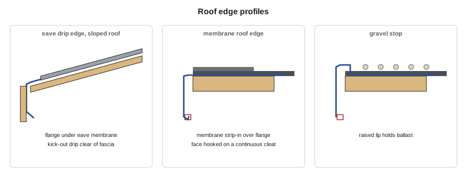
On a shingle, slate or metal-shingle roof, the eave and the rake edges get a drip edge: a bent strip with a flange that lies on the roof deck, a face that turns down over the fascia, and a kick-out or drip at the bottom that holds the water away from the fascia board. At the eave, the drip edge goes under the underlayment so water running down the underlayment lands on top of the metal. At the rake, the side edge of the roof, the drip edge goes over the underlayment so wind-driven rain is not pushed under it. That small difference is one of the most common errors on new roofs.
The eave detail also has to work with ice. In Halifax, as across most of the region, codes require an eave protection membrane, a self-adhered ice barrier, on shingle roofs, starting at the edge and running up the slope past the inside face of the exterior wall, because ice dams at the eave back water up under the shingles. The membrane laps over the drip edge flange at the eave, so any water backed up by ice runs out over the metal rather than behind it. Lesson 10 covers ice dams.
Edge metal on membrane roofs
Low-slope roofs, like the Ashgrove gym and the new Eastgate wing, are covered with a membrane: built-up asphalt, modified bitumen, or a single-ply sheet such as thermoplastic polyolefin or EPDM rubber. At the edge, the membrane laps up over a wood or metal nailer and down onto a metal edge flange. The edge metal is nailed or screwed through its flange into the nailer, then a strip of membrane is applied over the flange to seal it. The face of the edge turns down over the wall, and its bottom is hooked onto a continuous cleat, a strip fastened along the face of the blocking. Without the cleat, wind blowing up the wall can lift the face and peel the edge off like a lid.
A gravel stop is an edge with a raised lip on the flange, used on roofs with loose stone ballast or a gravel surfaced built-up roof, to keep the stones from washing or blowing off. A fascia system is a tall edge with a separate fascia cover snapped onto a continuous anchor bar, used where the edge face is deep or the architect wants a crisp line. Copings, which cover the top of a parapet, are covered in lesson 5.
Wind and edge testing
Roof edges are designed for wind uplift. Wind flowing over a building creates suction on the roof that is strongest at the corners and edges, often two or three times the suction in the field of the roof. The edge metal has to resist the outward pull on its face and the upward pull on the membrane behind it.
In Canada, the National Building Code requires the roof assembly to resist the specified wind load, and manufacturers of edge systems test them to show their resistance. Many designers and roofing specifications in Canada follow the North American edge test protocols published with ANSI/SPRI ES-1, which cover the face pull-off, the coping pull-off and the membrane hold-down; Keelson either installs a tested manufactured edge or builds a shop-made edge to the cleat and fastener spacing on the architect's details.
The practical lesson is that fastener spacing on an edge is not a craft choice. The tested assembly or the engineer's detail gives the cleat gauge, the cleat fastener spacing and the flange fastener spacing, and those spacings are usually tighter at the roof corners than along the middle of each side. Sean marks the corner zones on the roof with paint before the crew starts.
Developed width and shop forming
Edge pieces are formed on the brake from strip cut off a sheet or coil. The width of strip needed is the developed width: the sum of all the legs of the profile, plus allowances for hems and bends. For light-gauge architectural metal, Keelson uses the outside dimensions of the legs and adds a small allowance per hem, which is close enough for edge work; the precise bend allowance methods from SMW-110 are used only where a profile must fit something tightly.
Kai worked out the strip widths and the number of pieces for the Ashgrove gym roof edge, which runs along both long sides of the gym, 36.6 m each, with the legs on Lin's shop drawing.
# Developed width and piece count for a roof edge (illustrative profile)
legs = [100, 150, 25]        # flange, face, kick-out, mm
hems = 1        # number of hems
hem_allow = 12     # allowance per hem, mm
developed = sum(legs) + hems * hem_allow
print(f"developed width {developed:.0f} mm")
sheet_w = 1219       # sheet or coil width, mm
strips = int(sheet_w // developed)
print(f"strips per sheet width: {strips}, offcut {sheet_w - strips * developed:.0f} mm")
run = 73.2          # total edge length, m
piece = 3.05         # piece length, m
lap = 0.10          # end lap at each joint, m
pieces = 0
covered = 0.0
while covered < run:
    covered += piece if pieces == 0 else piece - lap
    pieces += 1
print(f"{run} m of edge needs {pieces} pieces of {piece} m with {lap} m laps")developed width 287 mm strips per sheet width: 4, offcut 71 mm 73.2 m of edge needs 25 pieces of 3.05 m with 0.1 m laps
Four strips came out of each sheet width, with a narrow offcut that Walt saves for small flashings. The piece count gave Lin the shop order; Sean added corner pieces and a few spares for damage in handling.
Joints along the edge
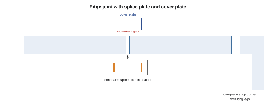
Edge pieces are joined end to end with a lap, a lap with a cover plate, or a butt joint with a concealed splice plate under it and a cover plate over it. Plain laps are fine for small, light-gauge drip edge. On membrane roof edges, where the face is wide and the membrane strips over the flange, the usual joint is a small gap of a few millimetres or about a quarter inch between pieces, to allow for movement, with a splice plate set in sealant underneath and a cover plate over the face. The gap matters: if two prefinished steel edge pieces are butted tight in winter, they will push each other into a bulge in summer.
Corners are made as single mitred pieces in the shop, with legs long enough to reach past the corner zone, so there is no field joint right at the corner where the wind load is highest. Lin details them on the shop drawings with a minimum leg length.
Fascias and soffits
Where the roof edge overhangs a wall, the fascia board and the soffit underneath are often clad in metal too, either as part of the edge system or as separate pieces. Soffit panels are usually vented to let air into the roof space, which matters for sloped roofs in cold climates and is covered in lesson 10. Fascia covers are formed to slide up under the drip edge face, so the drip edge laps the fascia cover and water cannot run behind it.
On the Ashgrove entrance canopy, the old painted wood fascia had rotted behind a metal cover that had been nailed straight through its face; every nail hole had let water into the wood for thirty years. The replacement cover hangs on a continuous cleat at the bottom and is held only at its top edge under the drip edge, with no exposed fasteners.
Matching the existing edge at St. Brendan's
On a heritage building, the edge profile is part of the building's character. St. Brendan's nave eaves end in a copper drip edge with a distinctive deep kick-out that throws water well clear of the stone cornice below. The original drip edge was formed by hand on a bench brake from 16 oz copper. The restoration uses the same profile, measured from a piece salvaged during the work, and the same weight of copper; lesson 11 explains how heritage profiles are recorded and matched.
Worked problem
Choosing the edge for each Keelson job
Which edge detail suits each roof?
Show solution
- St. Brendan's nave eave, a steep copper roof over a stone cornice: a copper drip edge with a deep kick-out, under the eave membrane, matching the original profile.
- Ashgrove gym, a low-slope modified bitumen roof on wood blocking: a prefinished steel membrane edge on a continuous cleat, with fastening to the tested spacing and tighter spacing at the corners.
- Eastgate wing, a low-slope single-ply roof with stone ballast: a manufactured gravel stop system tested for the design wind pressure.
- Ashgrove canopy, a sloped shingle roof: a prefinished drip edge at the eave under the underlayment and at the rakes over it.
Answer: The roof covering, the slope, the wind exposure and the building's character decide the edge.
Fastening edge metal into old and new blocking
Edge metal is only as strong as the blocking it is fastened to. On new roofs the blocking is treated lumber anchored to the structure at a designed spacing, and the edge fasteners are chosen to be compatible with the treatment, usually stainless or hot-dip galvanized ring-shank nails or screws. On reroofing jobs the existing blocking is often old, split or rotted, and nails into it hold almost nothing. At Ashgrove the crew probed the gym's blocking every metre or few feet before the edge went on, and the general contractor replaced two short lengths that crumbled; fastening into them would have looked fine and pulled out in the first storm.
Fasteners must also be long enough to reach sound wood through any tapered insulation or cant strips, and they must not split the blocking near its ends. Sean's checklist for the edge includes a pull test on a sample of fasteners in old blocking, done with a simple spring scale or a pull tester, so the crew knows the blocking is holding before covering it with the membrane strip-in.
Edges at gutters
Where a gutter hangs at the eave, the edge metal and the gutter must work together. The drip edge or the membrane edge face must drop into the gutter, inside its back, so water running off the roof lands in the gutter and not behind it. On membrane roofs with gutters, the edge is often a combined piece with an extended face that hangs into the gutter, and the gutter hangers are fastened through the edge flange into the blocking. Getting this joint wrong sends water down the fascia behind the gutter, which is one of the most common complaints on low-slope roofs with eave gutters.
Edges are also where other trades damage finished work. Roofers walking the edge to reach the membrane, ladders leaned on the face, and hoisting straps dragged over it all dent or scratch prefinished metal. Keelson installs edge metal as late in the roofing sequence as the membrane allows, puts temporary protection over the face where ladders will land, and walks the edge with the general contractor at handover so any damage by others is recorded before it becomes a Keelson repair.
Common mistakes
MistakeInstalling the rake drip edge under the underlayment.
InsteadAt the rake, put the drip edge over the underlayment; at the eave, under it.
MistakeLeaving the face of a membrane edge free at the bottom.
InsteadHook the face onto a continuous cleat so wind cannot lift it.
MistakeSpacing edge fasteners by eye.
InsteadUse the tested assembly's spacing, with tighter spacing in the corner zones.
MistakeButting prefinished edge pieces tight in winter.
InsteadLeave a small movement gap over a splice plate.
MistakeNailing a fascia cover through its face.
InsteadHang the cover on a cleat and hold it under the drip edge.
Summary and key terms
- Roof edges resist the highest wind suction on the roof and are a common failure point.
- Eave drip edge goes under the underlayment; rake drip edge goes over it.
- Membrane edges have a flange stripped in with membrane and a face held by a continuous cleat.
- Edge systems are designed and tested for wind; their fastener spacing is not optional.
- Joints have a movement gap with splice and cover plates; corners are one-piece mitres.
- Heritage edges are matched to the original profile and metal.
- Drip edge
- A bent edge strip on a sloped roof that carries water clear of the fascia.
- Rake
- The sloping side edge of a gable roof.
- Gravel stop
- A roof edge with a raised lip to retain loose ballast.
- Continuous cleat
- A strip fastened along the full length of an edge that the face hem hooks onto.
- Strip-in
- A strip of membrane applied over a metal flange to seal it to the roof.
- Corner zone
- The area at roof corners where wind suction is highest and fastening is tighter.
Practice problems
Work each problem on paper first, then reveal the answer to check.
Where does the drip edge go relative to the underlayment at the eave, and why?
Show answer
Under it, so water running down the underlayment lands on top of the metal.
What holds the bottom of a membrane edge face down?
Show answer
A continuous cleat that the face hem hooks onto.
An edge profile has legs of 100, 120 and 20 mm and one hem allowed at 12 mm. What strip width is needed?
Show answer
100 + 120 + 20 + 12 = 252 mm.
Why is the corner of an edge made as one shop piece?
Show answer
So there is no field joint in the corner zone, where wind load is highest.
Lesson quiz · 5 questions
Score 60% or more to complete this lesson.
Create a free account to save your progress, take quizzes and earn a certificate.