
ROB-499 · Lesson 7 of 12 · 28 min
Integration and the integration plan
Integration is where a robot becomes a robot, and where most capstone schedules break. Subsystems that each passed their bench tests start interfering with each other: the motors inject electrical noise into the IMU, the arm's swing shifts the centre of mass and the wheels slip, the perception node's processing delay makes the robot overshoot items, and the battery voltage sags when the arm and motors draw current together. This lesson covers how to plan integration so that problems appear one at a time, how to manage time and latency across a ROS 2 system, how to debug an integrated robot systematically, and how to keep a disciplined record of what was integrated and what was found.
Integration strategies
The worst strategy, and a common one, is big-bang integration: assembling everything at once in week 11 and switching it on. When it fails, as it will, there are too many possible causes to diagnose. Incremental integration adds one subsystem or capability at a time and tests after each step, so each new problem has a small number of candidate causes. Bottom-up integration starts with low-level components, such as motors, drivers and firmware, and builds upward. Top-down integration starts with the high-level software running against stubs or simulation and replaces stubs with real hardware one by one. Thread-based integration builds one end-to-end capability, such as "drive to a waypoint", across all layers, and then adds further threads.
Most robotics teams combine these approaches. Team Tern's plan used threads, each building on the last: first, teleoperated driving with the emergency stop and safety lidar; second, autonomous waypoint following with localization; third, litter detection while driving, with detections logged but not acted on; fourth, approaching a detected item and stopping in a grasp pose; fifth, grasping and depositing in the bin; and sixth, a full patrol with logging and reporting. Each thread has entry criteria, such as the subsystems it needs having passed bench tests, and exit criteria, such as a demonstration repeated five times in the test area. This sequence also means that if the term runs short, the robot is still useful at the last completed thread, which is the staged-concept idea from lesson 3 applied to integration.
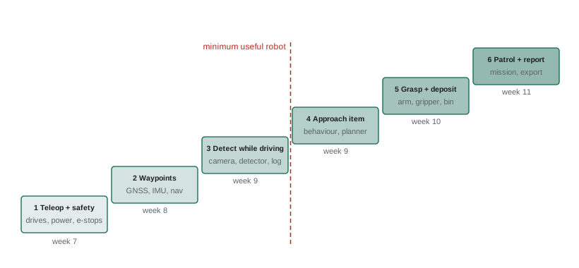
| Thread | Adds | Entry criteria | Exit criteria |
|---|---|---|---|
| 1 Teleop and safety | Chassis, drives, power, e-stops, safety lidar | Bench tests passed for mobility, power, safety | Protective stop verified 10 of 10; teleop on sand for 20 min |
| 2 Waypoint following | GNSS, IMU, odometry, localization, navigation | Thread 1 exit; nav tested in simulation | Follows 100 m route 5 times within 0.5 m |
| 3 Detection while driving | Camera, detector, logger | Thread 2 exit; detector passed dataset test | Detections logged with positions; recall checked on 30 seeded items |
| 4 Approach item | Behaviour logic, approach planner | Thread 3 exit | Stops in grasp pose within 5 cm for 8 of 10 items |
| 5 Grasp and deposit | Arm, gripper, bin, grasp planner | Thread 4 exit; gripper bench test passed | Grasps and deposits 7 of 10 cans |
| 6 Patrol and report | Mission manager, report export, status lights | Thread 5 exit | Completes a 45-min patrol and produces a correct report |
Preparing for integration
Integration goes faster when the groundwork is done. Before each thread, confirm that the subsystems have passed their bench tests, that the ICD is current and both sides agree on it, that software versions are tagged and recorded, that the integration test procedure is written, and that the test area, safety equipment and people are booked. An integration readiness checklist, reviewed in five minutes at the start of each session, prevents the familiar experience of spending the first two hours of a lab booking discovering that someone's branch was never merged or the battery was not charged.
Mechanical and electrical integration also need planning. Cable routing, connector access, service loops for moving parts, and access to fuses and batteries should be designed in, not improvised with cable ties at the end. Team Tern made a rule that nothing goes on the robot that is not in the master CAD assembly and the wiring diagram. When they added a status light late in the term, the change went through both documents first, and they discovered that the light's planned position blocked part of the lidar's field of view.
Time, synchronization and latency
An integrated robot is a distributed real-time system, and timing problems are among the most common integration surprises. Each sensor message carries a timestamp, and fusing data from several sensors only works if those timestamps share a clock. On a single computer, ROS 2 uses the system clock; across several computers, the clocks must be synchronized, typically with chrony using the Network Time Protocol, or with the Precision Time Protocol for tighter accuracy. Sensors with their own clocks, such as some lidars and GNSS receivers, need their timestamps converted or synchronized as well. A camera image timestamped 80 ms late will place every detection in the wrong position while the robot is moving.
Latency, the delay from an event in the world to the robot's response, determines how fast the robot can safely move and how accurately it can act. A latency budget, like the resource budgets in lesson 4, allocates the end-to-end delay across the pipeline: sensor exposure and transfer, perception, planning, control and actuation. Because each stage's delay varies, the budget should consider not only the average but the high percentiles; a pipeline that is fast on average but occasionally takes 400 ms can cause collisions or missed grasps. ROB-320 lesson 1 introduced latency budgets for embedded systems; here they are applied across the ROS 2 graph.
# End-to-end latency budget across Tern's ROS 2 pipeline (Monte Carlo, illustrative distributions)
import numpy as np
rng = np.random.default_rng(7)
N = 100_000
stages = {   # stage: samples in ms
    "camera exposure + USB": rng.normal(28, 3, N),
    "detector (GPU)":        rng.gamma(9.0, 6.0, N),            # mean 54 ms, long tail
    "3D projection + tf":    rng.normal(6, 1, N),
    "planner (10 Hz)":       rng.uniform(0, 100, N),            # 10 Hz planner: wait for next cycle
    "controller + serial":   rng.normal(12, 2, N),
    "motor response":        rng.normal(40, 5, N),
}
total = sum(stages.values())
for k, v in stages.items():
    print(f"{k:22s} mean {v.mean():6.1f} ms   p99 {np.percentile(v, 99):6.1f} ms")
p50, p95, p99 = np.percentile(total, [50, 95, 99])
print(f"end to end: median {p50:.0f} ms, p95 {p95:.0f} ms, p99 {p99:.0f} ms")
v = 0.5   # approach speed, m/s
print(f"distance moved during p99 latency at {v} m/s: {v * p99 / 1000 * 100:.1f} cm")
# effect of running the planner at 20 Hz instead of 10 Hz
total20 = total - stages["planner (10 Hz)"] + rng.uniform(0, 50, N)
print(f"with a 20 Hz planner: p99 {np.percentile(total20, 99):.0f} ms")camera exposure + USB mean 28.0 ms p99 34.9 ms detector (GPU) mean 54.0 ms p99 104.8 ms 3D projection + tf mean 6.0 ms p99 8.3 ms planner (10 Hz) mean 50.0 ms p99 99.0 ms controller + serial mean 12.0 ms p99 16.7 ms motor response mean 40.0 ms p99 51.6 ms end to end: median 190 ms, p95 246 ms, p99 267 ms distance moved during p99 latency at 0.5 m/s: 13.4 cm with a 20 Hz planner: p99 225 ms
The simulation shows two things. The largest contributors are the detector, whose processing time has a long tail, and the planner's waiting time: a 10 Hz planner may receive a detection just after it has run and wait up to 100 ms for its next cycle. At an approach speed of 0.5 m/s, the high-percentile latency means the robot moves roughly 13 to 14 cm between seeing an item and responding, which is larger than the 5 cm grasp-pose tolerance in thread 4's exit criteria. Running the planner at 20 Hz cuts the tail; slowing the final approach to 0.1 m/s cuts the distance travelled further; and predicting the item's position relative to the moving robot, using odometry and the image timestamp, removes most of the remaining error. Team Tern used all three. Without a latency budget, the symptom, the robot stopping a little past each item, would likely have been blamed on the detector or the arm.
Debugging an integrated robot
When something fails in integration, resist the urge to change several things at once. A systematic approach starts by reproducing the problem reliably, then narrowing it down by halving the system: does the problem occur in simulation? With recorded data? With the arm disconnected? With motors off? Each answer eliminates half the candidates. Change one thing at a time, keep notes, and when the cause is found, write a test that would have caught it.
ROS 2 provides good tools for this. ros2 topic hz and ros2 topic delay check rates and latencies against the ICD; ros2 node info and rqt_graph show the actual graph, which often reveals a misspelled topic name or a quality-of-service mismatch, for example a sensor publishing with best-effort reliability to a subscriber that requires reliable delivery, in which case no messages arrive. ros2 run tf2_tools view_frames and tf2_echo check the coordinate-frame tree, where a missing or inverted transform is a classic cause of detections appearing behind the robot. Recording everything with ros2 bag during integration sessions allows a problem seen once to be replayed and studied offline.
| Symptom | Common causes | First checks |
|---|---|---|
| Subscriber receives nothing | Topic name mismatch, QoS incompatibility, different ROS domain ID, network discovery issue | ros2 topic info -v; check QoS; check ROS_DOMAIN_ID |
| Detections appear in the wrong place | Wrong frame, inverted transform, timestamp offset, camera calibration | view_frames; compare timestamps; check calibration |
| Robot drifts or spins during localization | IMU noise from motors, wrong IMU orientation, encoder sign error | Plot raw IMU with motors on and off; check axes and signs |
| Random resets of the computer | Voltage sag when motors and arm draw current together | Log supply voltage; add capacitance or separate converter |
| Intermittent loss of serial link | Loose connector, ground loop, electrical noise, buffer overflow | Wiggle test; scope the line; check error counters |
| Works in the lab, fails outside | Sunlight on sensors, GNSS multipath, sand traction, temperature | Record field bags; compare with lab data |
Worked problem
Diagnosing random computer resets
During thread 5, Tern's computer reboots occasionally when the arm lifts a can while the robot is turning. What should the team check, and how?
Show solution
- Reproduce: command the arm lift during a turn on the test stand; the reset happens about one time in four.
- Hypothesis: the combined current draw of the motors and servos causes the supply voltage to sag below the computer's minimum input.
- Measure: log the computer's input voltage with an oscilloscope; it dips from 12 V to about 9.5 V for 15 ms during the event, below the computer's rated 11 V minimum.
- Fix: power the computer from its own DC-DC converter fed directly from the battery, add bulk capacitance near the servo supply, and verify that the dip at the computer is now under 0.3 V.
- Prevent recurrence: add the combined-load case to the power bench test and update the power architecture drawing.
Answer: A brown-out caused by shared supply rails; separating the computer's converter and adding capacitance fixed it, and the bench test now covers combined loads.
The integration log
Integration sessions should be logged like lab experiments. Each entry records the date, people present, configuration (hardware revision, firmware and software tags), what was attempted, what happened, any data recorded with file names, issues found and actions assigned. Issues go into the team's tracker with steps to reproduce. This record serves three purposes: it prevents the team from rediscovering the same problem, it provides evidence for the test report and the final report, and it gives examiners insight into the team's engineering process. A short integration log entry written at the end of each session takes ten minutes and repays itself many times over.
Integration also changes the plan. Problems found may require design changes, which go through the change log, updated budgets and, if they are large, a brief delta review with the advisor. The project buffer from lesson 5 exists precisely for this. Team Tern's integration of thread 5 took four days longer than planned because of the brown-out and a gripper alignment problem, and the buffer absorbed it. A team without buffer would have had to cut thread 6, the full patrol, which was what the partner most wanted to see.
If your robot connects to the partner's network or transmits data from a public place, check privacy expectations early. In Canada, municipal partners are generally covered by provincial public-sector privacy legislation, such as Ontario's Municipal Freedom of Information and Protection of Privacy Act, so images of members of the public collected by Tern may be subject to the partner's privacy obligations; lesson 9 discusses how to minimize and protect such data.
Common mistakes
MistakeIntegrating everything at once near the end of term.
InsteadIntegrate incrementally in threads with entry and exit criteria, starting as soon as subsystems pass bench tests.
MistakeStarting integration sessions without checking readiness.
InsteadUse a short readiness checklist covering merged code, tagged versions, charged batteries, procedures and safety equipment.
MistakeIgnoring clock synchronization between computers and sensors.
InsteadSynchronize clocks with chrony or PTP and check message timestamps during integration.
MistakeBudgeting latency by averages only.
InsteadModel and measure high percentiles, including waiting time for periodic nodes.
MistakeChanging several things at once when debugging.
InsteadReproduce the problem, halve the system to narrow the cause, change one thing at a time and record results.
MistakeRelying on memory of what happened in integration sessions.
InsteadKeep an integration log with configuration, results, data files and actions for every session.
Summary and key terms
- Incremental integration in threads with entry and exit criteria isolates problems and keeps the robot useful at each stage.
- Readiness checklists, current ICDs and designed-in cable routing make integration sessions productive.
- Clocks must be synchronized and timestamps correct for sensor fusion on moving robots.
- Latency budgets should consider high percentiles and the waiting time of periodic nodes.
- Systematic debugging reproduces, halves the system, changes one thing at a time and adds a test for each cause found.
- ROS 2 tools for rates, delays, graphs, QoS, transforms and bags are essential integration aids.
- An integration log records configurations, results, data and actions, providing evidence and preventing repeated mistakes.
- Big-bang integration
- Assembling all subsystems at once and testing the whole, which makes faults hard to isolate.
- Incremental integration
- Adding subsystems or capabilities one at a time with testing after each step.
- Integration thread
- An end-to-end capability built across all layers and integrated as a unit.
- Readiness checklist
- A short list of conditions confirmed before an integration session begins.
- Clock synchronization
- Aligning clocks across computers and sensors so timestamps are comparable.
- Latency budget
- An allocation of allowed delay across the stages of a sensing-to-actuation pipeline.
- Percentile latency
- The delay not exceeded in a given share of cases, such as 99 %.
- Quality of service
- ROS 2 settings such as reliability and durability that must be compatible between publishers and subscribers.
- Brown-out
- A temporary drop in supply voltage that can reset or disrupt electronics.
- Integration log
- A record of each integration session, its configuration, results and actions.
Practice problems
Work each problem on paper first, then reveal the answer to check.
Why does big-bang integration make debugging hard?
Show answer
Many new interactions appear at once, so a failure has too many possible causes to isolate.
Give the entry and exit criteria for a thread that adds the bin-full sensor.
Show answer
Entry: sensor bench-tested and in the ICD; thread 5 complete. Exit: bin-full state detected and reported correctly in, for example, 10 of 10 trials.
A camera on a second computer is 80 ms behind the main computer's clock. What happens to detections when the robot turns?
Show answer
Detections are transformed using the wrong robot pose and appear displaced; synchronize clocks or correct timestamps.
Why can a 10 Hz planner add up to 100 ms of latency?
Show answer
A detection arriving just after a planning cycle waits until the next cycle, up to one period later.
At 0.5 m/s, how far does the robot move during 270 ms of latency?
Show answer
\( 0.5 \times 0.27 = 0.135 \) m, about 13.5 cm.
Name three ways to reduce the effect of perception latency on approach accuracy.
Show answer
Increase planner rate, slow the final approach and predict the item's position using timestamps and odometry.
A subscriber receives no messages although the topic exists. Name two likely causes.
Show answer
Incompatible QoS settings, such as best effort versus reliable, or a different ROS domain ID; also a misspelled topic name.
Describe the halving approach to debugging.
Show answer
Repeatedly test the system with half the candidate causes removed or replaced, such as using recorded data or disconnecting a subsystem, to narrow the fault.
What should an integration log entry contain?
Show answer
Date, people, configuration and versions, what was attempted, results, data files, issues and actions.
Why did Team Tern's project buffer matter during integration?
Show answer
Thread 5 overran by four days; the buffer absorbed the delay so the full patrol thread was not cut.
Lesson quiz · 5 questions
Score 60% or more to complete this lesson.
Create a free account to save your progress, take quizzes and earn a certificate.