
ROB-330 · Lesson 3 of 12 · 30 min
Camera calibration
The camera model of lesson 2 is only as good as its numbers. A focal length that is 2 % wrong makes every distance a robot measures 2 % wrong; a principal point off by 15 pixels tilts every ray; an ignored distortion coefficient bends straight edges and throws pose estimates out by centimetres near the image border. Calibration is the process of estimating those numbers, the intrinsics and distortion coefficients, and often the camera's mounting on the robot as well. It is unglamorous work, but more robot vision projects fail through poor calibration than through poor algorithms. This lesson explains how calibration works, how to do it well, and how to tell whether the result can be trusted.
The idea: known points, measured pixels
Every calibration method follows the same plan. Show the camera points whose 3-D positions are known precisely, measure where they appear in the image, and adjust the camera parameters until the model's predicted pixel positions match the measured ones as closely as possible. The difference between measured and predicted pixel positions is the reprojection error, and calibration minimizes the sum of its squares over all points:
Here \( \mathbf{u}_{ij} \) is the measured pixel of target point j in image i, \( \pi \) is the full projection with distortion coefficients \( \mathbf{k} \), and each image has its own pose \( R_i, \mathbf{t}_i \) because the target moves between shots. This is a non-linear least-squares problem, solved with the Levenberg–Marquardt algorithm from a good starting estimate.
The known points usually come from a flat printed target. A checkerboard is the classic choice because its inner corners, where four squares meet, can be located to a small fraction of a pixel by fitting to the image gradients around them. Circle grids work too, and their centres can be found accurately, but perspective shifts the apparent centre of a circle slightly. ChArUco boards combine a checkerboard with ArUco markers in the white squares: each marker has a unique identity, so corners can be identified even when part of the board is out of view or occluded, which makes it far easier to get corners into the corners of the image, where distortion is strongest.
Zhang's method
The method most software uses, including OpenCV's calibrateCamera and the ROS camera_calibration package, was published by Zhengyou Zhang in 2000. Its insight is that a flat target makes the problem easier. If the target lies in the plane \( Z = 0 \) of its own frame, projection reduces to a 3 × 3 homography H between the target plane and the image:
Each image gives one homography, estimated linearly from at least four corner correspondences. Because the rotation columns \( \mathbf{r}_1 \) and \( \mathbf{r}_2 \) must be orthogonal and of equal length, each homography provides two linear constraints on the intrinsics. Three or more views of the target in different orientations give enough constraints to solve for K in closed form. With K known, each view's pose follows from its homography. That closed-form solution then seeds the full non-linear minimization, which also estimates the distortion coefficients.
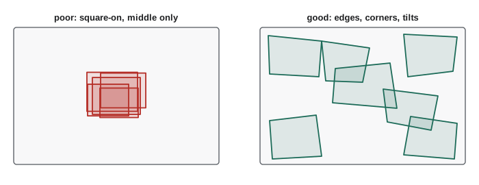
A practical consequence: the target must be seen at several different tilts. Images of a target held square-on to the camera, at different distances, give nearly identical constraints and leave the focal length poorly determined, because a closer target and a longer focal length look the same. Tilting the board by 30° to 45° in different directions breaks that ambiguity.
A calibration you can trust
Calibration software always returns numbers. Whether they are right depends on how the images were taken. A good session follows a few rules.
- Coverage: corners should appear across the whole image, especially near the edges and corners, where distortion is largest. A board that only ever fills the centre leaves the distortion model extrapolating.
- Variety of pose: include strong tilts about both axes and a range of distances, typically 20 to 50 images.
- Sharpness and exposure: avoid motion blur (hold the board still, or use a short exposure) and avoid saturated white squares, which shift detected corner positions.
- A flat, accurate target: print on a rigid backing such as aluminium composite or glass. A printed sheet taped to cardboard bows by millimetres, and the printer's scaling must be checked with a ruler, because the square size sets the metric scale of everything.
- The final configuration: calibrate with the focus, zoom and aperture locked at their working settings. Refocusing a lens changes its focal length and distortion.
Afterwards, check the results. The RMS reprojection error should typically be well under half a pixel for a good industrial camera, and under one pixel for most webcams. A low RMS is necessary but not sufficient: it can be low simply because the images covered too little of the field. Look at the per-image errors for outliers, check that the principal point is plausible, and verify on independent images, for example by measuring a known distance on a ruler or a second target at the working distance.
Worked problem
What does reprojection error mean in millimetres?
A camera with \( f_x = 1400 \) px has an RMS reprojection error of 0.3 px. How large is that error in the scene at a working distance of 0.6 m?
Show solution
- One pixel at depth Z spans \( Z/f_x = 0.6/1400 = 0.43 \) mm.
- Error: \( 0.3 \times 0.43 = 0.13 \) mm.
Answer: About 0.13 mm at 0.6 m, comfortably inside a typical pick-and-place tolerance of ±1 mm. At 3 m the same pixel error grows to about 0.64 mm.
import numpy as np
rng = np.random.default_rng(7)

# ground-truth camera
K_true = np.array([[1000.0, 0, 640], [0, 1000.0, 360], [0, 0, 1]])
ang = np.deg2rad(10)
R = np.array([[np.cos(ang), 0, np.sin(ang)], [0, 1, 0], [-np.sin(ang), 0, np.cos(ang)]])
t = np.array([0.05, -0.02, 1.0])
P_true = K_true @ np.hstack([R, t[:, None]])

# a 3-D calibration rig: points on two perpendicular planes, about 0.4 m across
g = np.linspace(-0.2, 0.2, 6)
A = [(x, y, 0.0) for x in g for y in g] + [(x, 0.0, z) for x in g for z in np.linspace(0.05, 0.3, 6)]
X = np.array(A)
Xh = np.hstack([X, np.ones((len(X), 1))])
uv = (P_true @ Xh.T).T
uv = uv[:, :2] / uv[:, 2:] + rng.normal(0, 0.3, (len(X), 2))   # 0.3 px detection noise

# Direct Linear Transform: two equations per point, solve A p = 0 by SVD
rows = []
for (Xw, Yw, Zw), (u, v) in zip(X, uv):
    p = [Xw, Yw, Zw, 1.0]
    rows.append(p + [0, 0, 0, 0] + [-u * c for c in p])
    rows.append([0, 0, 0, 0] + p + [-v * c for c in p])
_, _, Vt = np.linalg.svd(np.array(rows))
P = Vt[-1].reshape(3, 4)

# reprojection error
proj = (P @ Xh.T).T
proj = proj[:, :2] / proj[:, 2:]
err = np.linalg.norm(proj - uv, axis=1)
print("points:", len(X))
print("RMS reprojection error: %.3f px" % np.sqrt((err ** 2).mean()))

# recover K from P = K[R|t] with an RQ decomposition of the left 3x3 block
M = P[:, :3]
Q, Rm = np.linalg.qr(np.flipud(M).T)
Kest = np.flipud(np.fliplr(Rm.T))
Kest = Kest @ np.diag(np.sign(np.diag(Kest)))
Kest /= Kest[2, 2]
print("estimated fx, fy: %.1f, %.1f  (true 1000)" % (Kest[0, 0], Kest[1, 1]))
print("estimated cx, cy: %.1f, %.1f (true 640, 360)" % (Kest[0, 2], Kest[1, 2]))points: 72 RMS reprojection error: 0.364 px estimated fx, fy: 996.1, 995.2 (true 1000) estimated cx, cy: 640.5, 359.2 (true 640, 360)
The linear method recovers the intrinsics to within a fraction of a percent from 72 noisy points. Real calibration adds distortion and refines all parameters together by non-linear least squares, but the principle of matching predicted and measured pixels is the same.
Uncertainty in the calibration itself
Calibration results are estimates with uncertainty, and good tools report it. OpenCV's calibrateCameraExtended returns standard deviations for each intrinsic parameter, computed from the Jacobian of the reprojection error. A focal length of 1402.3 ± 0.4 px is a strong calibration; 1402 ± 25 px means the images did not constrain the focal length, usually through too little tilt. Correlations matter too: the principal point and the tangential distortion coefficients are strongly correlated, which is one reason many practitioners fix tangential distortion to zero unless the data clearly need it.
Worked problem
How much does a focal length error matter?
A robot estimates the distance to a 200 mm-wide box from its apparent width of 280 px, using \( Z = f_x W / w \). The calibrated focal length is 1400 px but the true value is 1428 px (2 % higher). What distance does the robot compute, and what is the true distance?
Show solution
- Computed: \( Z = 1400 \times 0.200/280 = 1.000 \) m.
- True: \( Z = 1428 \times 0.200/280 = 1.020 \) m.
Answer: The robot thinks the box is 1.000 m away when it is 1.020 m away: a 2 % focal length error produces a 2 % range error, 20 mm here, enough to make a gripper miss.
Extrinsic and hand-eye calibration
Intrinsics describe the camera; extrinsic calibration finds where it is mounted. For a camera fixed in a work cell, it is enough to find the transform from the robot base to the camera, for instance by having the robot touch known points on a target, or by observing a target held by the robot in several poses. For a camera on the robot's wrist, the problem is hand-eye calibration: find the fixed transform X from the gripper flange to the camera. Moving the arm between poses gives pairs of motions, A from the robot's forward kinematics and B from the camera's view of a fixed target, related by the classic equation
first solved by Tsai and Lenz in 1989, with many later methods. Each motion pair must include rotation about axes that are not parallel, otherwise parts of X remain unobservable. OpenCV's calibrateHandEye implements several solvers, and the ROS easy_handeye packages wrap the procedure. Errors in the robot's own kinematic calibration flow straight into X, so a hand-eye result is never more accurate than the arm that produced it.
Multi-camera rigs need the transforms between cameras as well. Stereo calibration (lesson 6) estimates the rotation and translation between two cameras by observing a target simultaneously with both, and a depth camera's colour and depth sensors have a similar factory calibration that should be checked.
Keeping calibration valid
A calibration describes one camera, lens and mounting at one moment. It degrades when any of those change. Knocks and vibration can shift a lens in its mount; temperature changes expand the lens barrel and bracket, shifting focal length and extrinsics measurably over a 30 °C swing; replacing a lens or even refocusing invalidates the intrinsics. Robots in production therefore include calibration checks: a fixed target or fiducial in the cell that the camera views periodically, with an alarm when its measured pose drifts beyond a threshold. Some systems refine calibration online, estimating small parameter changes from the scene itself, which is common in visual odometry and SLAM.
Worked problem
Planning a calibration target
A camera with a 60° by 45° field of view will be calibrated at its working distance of 0.8 m. What image area does the scene cover, and how large should a checkerboard be to fill about half the width in a single view?
Show solution
- Width at 0.8 m: \( 2 \times 0.8 \times \tan 30^{\circ} = 0.924 \) m.
- Height: \( 2 \times 0.8 \times \tan 22.5^{\circ} = 0.663 \) m.
- Half the width: about 0.46 m.
Answer: The view is about 0.92 m by 0.66 m, so a board about 450 mm wide, such as 9 by 6 squares of 50 mm, works well. Moving it across the field and tilting it then puts corners into every region of the image.
Common mistakes
MistakeTaking every calibration image with the board square-on to the camera
InsteadTilt the board 30° to 45° in several directions so the focal length is well constrained.
MistakeKeeping the board in the middle of the image
InsteadMove it so corners reach the edges and corners of the frame, where distortion is largest.
MistakeTrusting a low RMS reprojection error on its own
InsteadCheck per-image errors, parameter uncertainties and an independent measurement.
MistakeRefocusing or changing the aperture after calibration
InsteadLock focus, zoom and aperture at the working settings before calibrating.
MistakeUsing a paper target taped to cardboard without checking its size and flatness
InsteadUse a rigid, flat board and measure the printed square size.
Summary and key terms
- Calibration estimates intrinsics, distortion and often mounting transforms by minimizing reprojection error.
- Checkerboard corners can be located to sub-pixel accuracy; ChArUco boards allow partial views.
- Zhang's method uses one homography per view of a flat target to solve for K, then refines everything by non-linear least squares.
- Good data need full image coverage, strong tilts, sharp images, a flat accurate target and locked lens settings.
- Report parameter uncertainties and verify on independent measurements, not just RMS error.
- Hand-eye calibration solves \( AX = XB \) from robot motions and camera observations with non-parallel rotation axes.
- Calibration drifts with knocks, temperature and lens changes, so production systems check it periodically.
- Calibration
- Estimating a camera model's parameters from known points and measured pixels.
- Reprojection error
- The distance between a measured pixel and the model's predicted pixel.
- Checkerboard target
- A flat pattern whose inner corners serve as precisely known points.
- ChArUco board
- A checkerboard with uniquely identifiable ArUco markers in its squares.
- Zhang's method
- Calibration from several views of a planar target using homographies.
- Homography
- A 3 × 3 projective mapping between two planes.
- Levenberg–Marquardt
- An algorithm for non-linear least-squares minimization.
- DLT
- Direct linear transform: a linear solution for a projection matrix from correspondences.
- Hand-eye calibration
- Finding the transform between a robot's flange and a camera mounted on it.
- Extrinsic calibration
- Finding a camera's pose relative to the robot or another sensor.
Practice problems
Work each problem on paper first, then reveal the answer to check.
What quantity does calibration minimize?
Show answer
The sum of squared reprojection errors.
How many constraints on K does each view of a planar target give in Zhang's method?
Show answer
Two.
What is the minimum number of views for Zhang's closed-form solution with skew?
Show answer
Three.
Why tilt the target?
Show answer
To separate focal length from distance, which square-on views cannot.
One pixel at 1 m with \( f_x = 1000 \) spans how much?
Show answer
1 mm.
Name a target that tolerates partial views.
Show answer
A ChArUco board.
Write the hand-eye calibration equation.
Show answer
\( AX = XB \).
Why must hand-eye motions include non-parallel rotation axes?
Show answer
Otherwise parts of the transform cannot be observed.
Give two causes of calibration drift.
Show answer
Knocks or vibration, temperature changes, lens refocusing or replacement.
What does a large standard deviation on \( f_x \) suggest?
Show answer
The images did not constrain it, usually through too little tilt.
Lesson quiz · 5 questions
Score 60% or more to complete this lesson.
Create a free account to save your progress, take quizzes and earn a certificate.