
ROB-300 · Lesson 10 of 12 · 38 min
Force control: impedance, admittance and hybrid control
Everything so far has controlled motion in free space. Many of the most valuable robot tasks involve contact: inserting a peg, polishing a surface, assembling parts, opening a door, handing an object to a person, or a legged robot's foot striking the ground. In contact, pure position control is a poor idea. A stiff position controller pressed against a rigid surface with even a millimetre of position error generates enormous forces, and a small error in the modelled location of a part can break the part or the robot. Force control regulates the interaction itself: the force exerted, or the relationship between force and motion. This lesson covers the contact model, direct force control, impedance and admittance control, which shape the robot's apparent mechanical behaviour, hybrid position/force control, and the stability problems peculiar to contact.
Contact as a spring
The simplest model of a contacted environment is a spring of stiffness \( k_e \) located at position \( x_e \): when the tool penetrates by \( x - x_e > 0 \), the environment pushes back with force \( F = k_e(x - x_e) \). Real stiffnesses span a vast range: a sponge might be 100 N/m, a human hand 1,000 to 5,000 N/m, wood or a plastic part around \( 10^5 \) N/m, steel in contact effectively \( 10^6 \) N/m or more once the robot's own structure is included. The ratio of the robot's controlled stiffness to the environment's stiffness largely decides who 'wins' in contact: a soft controller against a hard environment controls force well and position poorly; a stiff controller against a soft environment controls position well and force poorly.
Worked problem
Force from a small position error
A position-controlled robot with an effective servo stiffness of 2 × 10⁵ N/m at the tool presses a part whose actual location is 1.5 mm closer than the model says. The part and fixture have stiffness 5 × 10⁵ N/m. Estimate the contact force.
Show solution
- The servo stiffness and environment stiffness act in series against the 1.5 mm position error.
- Combined stiffness: \( k = (2 \times 10^5)(5 \times 10^5)/(7 \times 10^5) = 1.43 \times 10^5 \) N/m.
- Force: \( F = 1.43 \times 10^5 \times 0.0015 = 214 \) N.
Answer: About 214 N, the weight of a 22 kg mass, from a 1.5 mm mistake. A force-controlled or compliant robot would limit this to whatever force was intended, perhaps 10 to 20 N.
Mapping forces to joint torques
Forces at the tool relate to joint torques through the transpose of the manipulator Jacobian (ROB-210): a wrench \( \mathbf{F} \) at the end effector requires joint torques
This follows from virtual work: the power at the joints, \( \boldsymbol{\tau}^{\mathsf{T}}\dot{\mathbf{q}} \), must equal the power at the tool, \( \mathbf{F}^{\mathsf{T}}\dot{\mathbf{x}} = \mathbf{F}^{\mathsf{T}}\mathbf{J}\dot{\mathbf{q}} \). The relation lets a torque-controlled robot apply a chosen force without any force sensor, provided friction and the dynamic model are well known, and lets a force sensor reading be expressed as joint torques. Near singularities, \( \mathbf{J}^{\mathsf{T}} \) maps large tool forces to small joint torques in some directions, which is why a nearly straight arm can resist huge forces along its length.
Worked problem
Joint torques for a tool force
A planar two-link arm with \( l_1 = 0.4 \) m, \( l_2 = 0.3 \) m is at \( q_1 = 0 \), \( q_2 = 90° \). The tool must press downward with 20 N (F = [0, −20] N). Find the joint torques, ignoring gravity.
Show solution
- Jacobian (ROB-210): \( \mathbf{J} = \begin{bmatrix} -l_1s_1 - l_2s_{12} & -l_2s_{12} \\ l_1c_1 + l_2c_{12} & l_2c_{12} \end{bmatrix} \).
- At \( q_1 = 0 \), \( q_1 + q_2 = 90° \): \( s_1 = 0, c_1 = 1, s_{12} = 1, c_{12} = 0 \). \( \mathbf{J} = \begin{bmatrix} -0.3 & -0.3 \\ 0.4 & 0 \end{bmatrix} \).
- \( \boldsymbol{\tau} = \mathbf{J}^{\mathsf{T}}\mathbf{F} = \begin{bmatrix} -0.3 & 0.4 \\ -0.3 & 0 \end{bmatrix}\begin{bmatrix} 0 \\ -20 \end{bmatrix} = \begin{bmatrix} -8 \\ 0 \end{bmatrix} \) N·m.
Answer: τ = [−8, 0] N·m. Only the shoulder works: the downward force passes through the elbow axis line when link 2 points straight up, so the elbow carries none of it. Gravity compensation torques would be added on top.
Direct force control
When the task is to hold a specified contact force, for example pressing a polishing tool with 15 N, the simplest approach measures the force with a wrist force/torque sensor and closes a loop on the force error. Because the contact force is proportional to penetration, a force loop through a position-controlled robot is effectively a loop on position with gain \( k_e \): stiff environments make the loop gain high and threaten stability, soft environments make it sluggish. Integral action is usually included to remove steady force error, and the force signal is filtered because force sensors are noisy. Direct force control works when the robot is always in contact; it behaves badly during the transition from free space to contact, when there is no force to feed back and the robot accelerates toward the surface until it hits.
Impedance control
Impedance control, formulated by Neville Hogan in 1985, takes a different view: rather than controlling force or position, control the dynamic relationship between them. The robot is made to behave like a chosen mass-spring-damper system attached to a reference trajectory \( \mathbf{x}_r \):
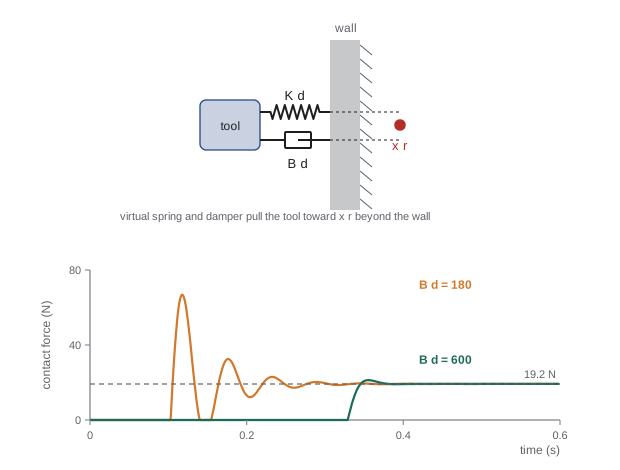
In free space, with no external force, the robot follows the reference like a position controller. In contact, it yields like a spring, and the force it exerts is set by the stiffness and the penetration of the reference into the surface. The same controller handles both phases and the transition between them, which is its great advantage. A simple implementation on a torque-controlled robot, with the desired inertia left as the robot's own and gravity compensated, is
a Cartesian PD law mapped to joint torques. This is how collaborative arms with joint torque sensing provide their compliant, safe behaviour: a person pushing the arm feels a spring and damper, not a rigid machine. Stiffness and damping can be set separately for each direction, for example stiff in the plane of a surface and compliant normal to it.
Worked problem
Contact force under impedance control
A robot under impedance control with \( K_d \) = 2,000 N/m normal to a surface is commanded to a reference 10 mm beyond the surface. The surface stiffness is 5 × 10⁴ N/m. Find the steady contact force and the actual penetration.
Show solution
- At rest, the virtual spring and the surface are in series. Let p be the penetration and d = 0.010 m the reference offset.
- Force balance: \( K_d(d - p) = k_ep \), so \( p = K_dd/(K_d + k_e) = 20/52{,}000 = 3.85 \times 10^{-4} \) m.
- Force: \( F = k_ep = 19.2 \) N.
Answer: About 19.2 N with only 0.38 mm penetration. Because the surface is 25 times stiffer than the controller, the force is set almost entirely by the controller: \( F \approx K_dd = 20 \) N. To press with 15 N, place the reference about 7.5 mm beyond the surface. Errors of a few millimetres in the surface location change the force by only a few newtons.
Admittance control
Impedance control needs a robot whose joint torques can be commanded accurately: direct-drive, low-ratio or torque-sensed joints. Most industrial robots have stiff position controllers behind high-ratio gearboxes and do not accept torque commands. For them, admittance control inverts the causality. A force/torque sensor measures the contact force, a virtual dynamic model computes the motion that a mass-spring-damper would make in response, and that motion is sent to the robot's position controller:
where \( \mathbf{x}_c \) is the commanded position, integrated in software at each control step. Impedance and admittance control are complementary. Impedance control renders soft behaviour well but struggles to render high stiffness, because the robot's own friction and limited torque bandwidth get in the way. Admittance control renders stiff behaviour well, since the inner position loop is stiff, but is prone to instability when rendering low inertia and damping against stiff environments: the force loop gain becomes too high. Hand-guiding of industrial robots through a wrist force sensor, a common way to teach positions, uses admittance control with low virtual mass and damping in free space.
Worked problem
Admittance velocity response
An admittance controller for hand guiding uses \( M_d \) = 5 kg, \( B_d \) = 50 N·s/m and \( K_d \) = 0. An operator pushes with a steady 15 N. Find the steady commanded speed and how long it takes to reach 63 % of it.
Show solution
- With \( K_d \) = 0, steady state has \( \ddot{x}_c = 0 \), so \( B_d\dot{x}_c = F \): \( \dot{x}_c = 15/50 = 0.3 \) m/s.
- The speed responds as a first-order system with time constant \( M_d/B_d = 0.1 \) s.
Answer: The robot glides at 0.3 m/s, reaching 63 % of that speed in 0.1 s. Halving \( B_d \) would double the speed per newton and feel lighter, but would bring the loop closer to instability if the operator stiffens their arm.
Hybrid position/force control
Many tasks need position control in some directions and force control in others at the same time. Wiping a table requires pressing down with a controlled force while moving across the surface along a position trajectory. Raibert and Craig's hybrid position/force control, from 1981, splits task space with a diagonal selection matrix S, with ones in the force-controlled directions and zeros in the position-controlled ones:
Here \( \mathbf{F}_{\text{force}} \) comes from a force loop and \( \mathbf{F}_{\text{position}} \) from a position loop, both expressed in a task frame aligned with the contact, for example with z normal to the surface. The choice follows the natural constraints of the task: where the environment prevents motion, control force; where it prevents force (free directions), control position. A peg-in-hole insertion controls force along the hole axis and lateral position, while allowing small lateral compliance so the peg can centre itself. A known difficulty is that the selection must match the actual contact geometry; if the surface is tilted relative to the assumed task frame, the force and position loops fight each other.
Worked problem
Selection matrix for wiping
A robot wipes a horizontal table, moving in x and y while pressing with 12 N in −z, and keeping the tool orientation fixed. Write the translational selection matrix and the force set-point.
Show solution
- Force-controlled direction: z. Position-controlled: x, y.
- \( \mathbf{S} = \text{diag}(0, 0, 1) \) for translation; orientation is position-controlled.
- Force set-point: \( F_z = -12 \) N; x and y follow the wiping trajectory.
Answer: S = diag(0, 0, 1) with \( F_{z,\text{ref}} \) = −12 N. If the table were tilted 5° and the task frame were not rotated to match, part of the 12 N would push along the surface and part of the position motion would push into it.
Contact stability and passivity
Contact makes control harder for three reasons. First, the environment stiffness multiplies the loop gain, as in direct force control, so a loop tuned in free space can go unstable against a hard surface. Second, the instant of impact is a discontinuity: the robot arrives with momentum, and a stiff, poorly damped controller bounces, repeatedly losing and regaining contact, a behaviour called chatter. Third, sampling, delay and sensor filtering, all harmless in free space, can turn a nominally stable contact unstable because the stiff contact has a high natural frequency, \( \omega_c = \sqrt{(K_d + k_e)/m} \), possibly above the controller's ability to respond.
A powerful design principle is passivity: if the controlled robot, seen from its contact point, never generates net energy, it will remain stable when coupled to any passive environment, whether soft, hard, or a human. Impedance controllers with positive stiffness and damping are passive in continuous time; digital implementation adds energy through sampling, which limits the stiffness that can be rendered stably for a given sample rate and damping. A widely cited guideline from haptics, the work of Colgate and colleagues in the 1990s, states that a virtual wall of stiffness K rendered with sample time T and damping B, on a device with physical damping b, is passive when \( b > KT/2 + B \), where B here is the virtual damping in the discrete implementation. Ordinary engineering practice is to add damping, lower stiffness near contact, approach surfaces slowly, and filter force signals with care.
Worked problem
Contact natural frequency and sample rate
A tool of effective mass 4 kg under impedance control with \( K_d \) = 2,000 N/m contacts a surface of stiffness 5 × 10⁴ N/m. Find the contact natural frequency and the minimum sensible control rate.
Show solution
- \( \omega_c = \sqrt{(2{,}000 + 50{,}000)/4} = \sqrt{13{,}000} = 114 \) rad/s, or 18 Hz.
- A controller should run at least 10 to 20 times faster than the dynamics it must damp: 180 to 360 Hz, and in practice 1 kHz.
Answer: About 18 Hz, so a control rate of 1 kHz is appropriate. Against a steel surface of \( 10^6 \) N/m, the contact frequency would rise to about 80 Hz, which is why stiff contact tasks often need dedicated high-rate force loops or passive compliance in the tool.
import numpy as np
m, Kd, ke, xe = 4.0, 2000.0, 5.0e4, 0.0            # tool mass, impedance stiffness, wall at x = 0
def contact(Bd, h=1e-5, T=0.6):
    x, v, xr = -0.02, 0.0, 0.010                   # start 20 mm before wall, reference 10 mm into it
    Fpeak = 0.0; bounces = 0; incontact = False
    for k in range(int(T/h)):
        Fe = ke*(x - xe) if x > xe else 0.0         # wall force on tool, pushing back
        if (x > xe) and not incontact: bounces += 1
        incontact = x > xe
        F = Kd*(xr - x) - Bd*v - Fe
        v += h*F/m; x += h*v
        Fpeak = max(Fpeak, Fe)
    return Fpeak, Fe, bounces
for Bd in (20.0, 180.0, 600.0):
    Fpk, Fend, nb = contact(Bd)
print(f"Bd = {Bd:5.0f} N s/m: peak force {Fpk:6.1f} N, final {Fend:5.1f} N, contacts made {nb}")Bd = 20 N s/m: peak force 256.9 N, final 0.0 N, contacts made 5 Bd = 180 N s/m: peak force 66.9 N, final 19.2 N, contacts made 2 Bd = 600 N s/m: peak force 21.3 N, final 19.2 N, contacts made 1
With light damping the tool strikes the wall at over 250 N, bounces off and is still chattering against it after 0.6 s; with moderate damping the peak falls to about 67 N and the tool bounces once before settling at 19.2 N; with heavy damping the approach is slow and the force rises almost without overshoot to the 19.2 N predicted by the series-spring calculation. Approach speed and damping, more than stiffness, decide the impact force.
Common mistakes
MistakeUsing stiff position control for contact tasks
InsteadSmall position errors then cause very large forces; use impedance, admittance or force control.
MistakeUsing direct force control during the approach to contact
InsteadWith no contact there is no force to regulate; impedance control handles both phases.
MistakeRendering low virtual inertia with admittance control against stiff surfaces
InsteadAdmittance loops destabilize with stiff contact; raise virtual mass and damping.
MistakeAssuming the hybrid task frame matches the real contact
InsteadAlign the selection with the actual surface or the force and position loops conflict.
MistakeIgnoring sampling and filtering in contact
InsteadContact frequencies can be high; use adequate rates, damping and passivity-based limits.
Summary and key terms
- Contact can be modelled as a spring; the ratio of controller to environment stiffness decides whether force or position is well controlled.
- Tool forces map to joint torques through \( \boldsymbol{\tau} = \mathbf{J}^{\mathsf{T}}\mathbf{F} \).
- Direct force control closes a loop on measured force but handles the free-space approach poorly.
- Impedance control makes the robot behave like a mass-spring-damper about a reference, handling free motion and contact alike.
- Admittance control computes motion from measured force and suits stiff, position-controlled industrial robots.
- Hybrid control uses a selection matrix to control force in constrained directions and position in free ones.
- Contact stability depends on environment stiffness, impact, sampling and delay; passivity is a guiding design principle.
- Environment stiffness
- The spring constant relating penetration to contact force.
- Jacobian transpose
- The matrix mapping tool forces to joint torques.
- Direct force control
- Feedback on measured contact force error.
- Impedance control
- Controlling the dynamic relationship between motion and force at the tool.
- Admittance control
- Computing commanded motion from measured force through a virtual dynamic model.
- Hybrid position/force control
- Controlling force and position in complementary task directions.
- Selection matrix
- A diagonal matrix choosing force- or position-controlled directions.
- Natural constraints
- Directions where the environment restricts motion or force.
- Chatter
- Repeated loss and regain of contact after impact.
- Passivity
- The property of never generating net energy, which ensures stable interaction.
Practice problems
Work each problem on paper first, then reveal the answer to check.
Series stiffness of 10⁴ and 10⁴ N/m?
Show answer
5,000 N/m.
A robot with \( K_d \) = 1,000 N/m presses a rigid wall with reference 15 mm inside. Approximate force?
Show answer
About 15 N.
Write the joint torque for a tool force F.
Show answer
\( \tau = J^{\mathsf{T}}F \).
Which control approach suits a stiff industrial robot with a wrist force sensor?
Show answer
Admittance control.
Which suits a torque-controlled collaborative arm?
Show answer
Impedance control.
Admittance with \( B_d \) = 40 N·s/m and push 8 N, \( K_d \) = 0. Steady speed?
Show answer
0.2 m/s.
Selection matrix for inserting a peg along z with lateral position control?
Show answer
S = diag(0, 0, 1).
Contact frequency for m = 2 kg, total stiffness 20,000 N/m?
Show answer
100 rad/s, about 16 Hz.
What reduces impact force most?
Show answer
Lower approach speed and more damping.
Why is passivity useful?
Show answer
A passive robot stays stable against any passive environment, including people.
Lesson quiz · 5 questions
Score 60% or more to complete this lesson.
Create a free account to save your progress, take quizzes and earn a certificate.