
RAC-420 · Lesson 4 of 12 · 17 min
Compressors, vessels and oil management in ammonia plants
Grand Valley's engine room held five screw compressors: three high-stage machines and two boosters, each on a skid with its own motor, oil separator, oil cooler, oil pump, filters and control panel. On the wall, Luis kept a whiteboard with each compressor's running hours and the oil added that month. In February, Theo noticed that one number stood out. High-stage compressor 3 had taken nearly three times as much oil as the others. "Good," Ingrid said. "Now find out where it's going." This lesson describes the compressors and vessels of an industrial ammonia plant, how they share the load in a two-stage system, and why oil management is both an efficiency and a safety task.
Screw compressors
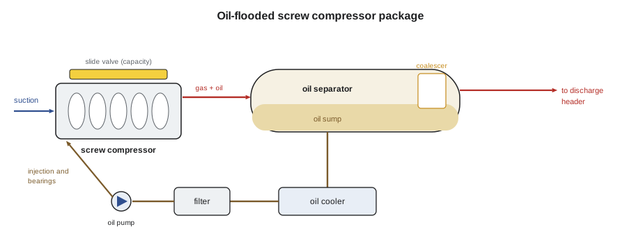
Most industrial ammonia plants built in the last forty years use oil-flooded twin-screw compressors. Two meshing rotors, one male and one female, trap vapour in the spaces between their lobes and the casing and carry it from the suction end to the discharge end, where the shrinking volume compresses it. Oil is injected into the compression space in large quantities: it seals the clearances between the rotors and the casing, lubricates the bearings and absorbs the heat of compression, which keeps the discharge temperature down even across high pressure ratios. Capacity is controlled by a slide valve that moves along the rotors to shorten the effective compression length, typically from about 10 % to 100 %, and often by variable-speed drives.
Because the compression happens inside the rotors, a screw compressor has a built-in volume ratio, set by the shape of its discharge port. If the plant's actual pressure ratio is higher or lower than the ratio the compressor is built for, the gas is over- or under-compressed at discharge and energy is wasted. Many industrial screws have a variable volume ratio feature, a second slide that adjusts the discharge port, so that the compressor matches changing conditions. Older plants often still have reciprocating compressors for smaller duties, with their own oil pumps and crankcases; they are efficient at full load and need more maintenance.
Every screw compressor package has an oil system. The discharge gas, carrying oil, enters an oil separator, a large vessel where the oil drops out by impingement, a change in direction and velocity, and, in the final stage, coalescing filter elements. The separated oil collects in the sump, passes through an oil cooler, which may be water-cooled, refrigerant-cooled by thermosiphon from the receiver, or cooled by liquid injection into the compressor, then through filters, and returns to the compressor's bearings and injection ports. Sensors monitor oil pressure, oil temperature, filter pressure drop and separator level, and the controls stop the compressor on any fault.
How the stages share the load
In a two-stage plant, the high stage does not just carry the coolers and docks. It also carries everything the booster delivers: the freezer load plus the heat of compression the boosters added. That is why high-stage compressors are much larger than the loads at the intermediate level alone would suggest. The script estimates Grand Valley's energy balance using a simple efficiency model, a fixed fraction of the ideal Carnot efficiency, and compares it with a single-stage freezer.
# Two-stage energy balance and a screw compressor oil log (illustrative)
def cop(te, tc, eff=0.45):                   # a fraction of the Carnot COP, temperatures in C
    return eff * (te + 273.15) / (tc - te)
booster_load, high_load = 1400.0, 700.0      # kW
cb = cop(-35, -5)
wb = booster_load / cb
ch = cop(-5, 35)
high_total = booster_load + wb + high_load   # the high stage also carries the booster's load and heat of compression
wh = high_total / ch
print(f"booster COP {cb:.2f}, power {wb:.0f} kW")
print(f"high stage carries {high_total:.0f} kW, COP {ch:.2f}, power {wh:.0f} kW")
print(f"condenser rejects {high_total + wh:.0f} kW; total input {wb + wh:.0f} kW")
single = booster_load / cop(-35, 35, 0.32) + high_load / cop(-5, 35)   # one screw across a ratio of 14.5 is far less efficient
print(f"single-stage freezer with the same coolers would need about {single:.0f} kW ({single / (wb + wh) - 1:.0%} more)")
# litres of oil added per 1,000 running hours, by compressor
log = {"HS-1": (12, 3100), "HS-2": (11, 2950), "HS-3": (31, 3050), "B-1": (9, 4200), "B-2": (10, 4150)}
for name, (litres, hours) in log.items():
    rate = litres / hours * 1000
    flag = "  <- check separator, coalescer and oil level controls" if rate > 6 else ""
print(f"{name}: {rate:4.1f} L per 1,000 h{flag}")booster COP 3.57, power 392 kW high stage carries 2492 kW, COP 3.02, power 826 kW condenser rejects 3318 kW; total input 1218 kW single-stage freezer with the same coolers would need about 1518 kW (25% more) HS-1: 3.9 L per 1,000 h HS-2: 3.7 L per 1,000 h HS-3: 10.2 L per 1,000 h <- check separator, coalescer and oil level controls B-1: 2.1 L per 1,000 h B-2: 2.4 L per 1,000 h
With 1,400 kW of freezer load and 700 kW of cooler and dock load, the boosters drew about 390 kW, and the high stage had to carry about 2,490 kW, the freezer load, the booster power and its own loads, drawing about 830 kW. The evaporative condenser rejected about 3,300 kW. A single-stage freezer, across a pressure ratio of about 14.5, would have needed about a quarter more power. The numbers come from a simplified model, but they show why the high stage is the plant's largest energy user and why a booster running inefficiently costs twice: once in its own power and again in the high stage's.
The vessels
Industrial ammonia plants are built around pressure vessels, each with a specific job.
- The high-pressure receiver stores liquid from the condenser and supplies the plant. It holds the largest single share of the charge and is sized to hold most of the plant's ammonia when evaporators and vessels are pumped down for maintenance.
- Recirculators, or pumper drums, separate liquid and vapour on the low side and supply the liquid pumps, as lesson 3 described.
- The intercooler, in two-stage plants, cools booster discharge gas and subcools liquid.
- Suction accumulators, or knock-out drums, protect compressors from liquid in systems without recirculators.
- Thermosiphon receivers and oil pots, and controlled pressure receivers in some modern designs, serve particular functions.
All of these are designed, built and stamped to the CSA B51 boiler, pressure vessel and pressure piping code and ASME Section VIII, registered with TSSA in Ontario, and inspected under Ontario's boiler and pressure vessel rules. They carry nameplates with their design pressure and temperature, and they must have pressure relief devices, as lesson 5 describes. Vessels are inspected regularly for corrosion, especially under insulation, where moisture trapped against cold steel can eat through a wall unseen; that kind of corrosion has caused major releases. IIAR 6 sets out the inspection and testing tasks and frequencies for vessels, piping, valves and relief devices.
Level controls and safety switches on vessels are among the plant's most important instruments. High-level switches on recirculators, intercoolers and accumulators stop compressors before liquid can be drawn into them, which would wreck a compressor and can rupture it. Level transmitters let the operators see what is happening, and level columns with sight glasses or magnetic gauges provide a direct check. Operators record vessel levels on their rounds, and a change in the normal levels is one of the first signs of a problem, as lesson 8 shows.
Oil in ammonia plants
Oil behaves very differently in ammonia systems from in fluorocarbon systems. The mineral and synthetic oils used with ammonia are almost insoluble in liquid ammonia, and they are heavier than it. Any oil that gets past the separators therefore does not travel around the system dissolved in the refrigerant and return to the compressor, as it does in an HFC system. It separates out and settles at the low points of the low side: in recirculators, intercoolers, surge drums, evaporators and liquid legs, where it forms a layer at the bottom. At low temperatures it becomes thick and waxy. Oil on evaporator tube walls insulates them and reduces capacity, and oil in a recirculator can be drawn into the pumps.
For that reason ammonia plants do not rely on oil returning; they remove it. Oil separators are made as efficient as possible, so that little oil leaves the compressor packages, and oil that does get through is drained from the low points periodically, through oil pots and drain valves, by the procedure in lesson 8. Every litre of oil added to a compressor is either still in the separator, burnt or degraded, or somewhere else in the plant. The oil log is how a plant keeps track.
High-stage 3 was using about 10 litres per 1,000 running hours, against 4 for its two sisters. With Luis's operators, Ingrid and Theo checked the separator's oil level controls, which were working, then shut the compressor down, isolated and pumped it out under the plant's procedure, and opened the separator. The coalescing elements were split along a seam, so oil mist was going straight through to the discharge header and on to the condenser and receiver. New elements brought the rate back to about 4 L per 1,000 hours, and the plant scheduled extra oil draining from the intercooler for the next month to remove what had already gone downstream.
Oil also tells the plant about its compressors. Samples are taken from each compressor's oil system on a schedule and sent for analysis of viscosity, water content, acidity, wear metals and contaminants, as RAC-410 described for chillers. Ammonia plants also watch for oil degradation from high discharge temperatures, and for water in the oil, which may point to water in the refrigerant.
Liquid pumps and their care
The recirculation pumps that feed liquid overfeed systems are usually sealless canned-motor or magnetic-drive pumps, in which the motor's rotor runs in the pumped ammonia inside a sealed can, so there is no rotating shaft seal to leak. They are reliable but depend on the liquid for cooling and lubrication of their bearings, so they must never run dry or with flashing liquid. Their protection includes low-differential-pressure switches, which stop a pump that is not developing pressure, and minimum-flow bypasses. Strainers at their inlets catch scale and debris from the vessel and must be cleaned with the pump isolated and pumped out. A pump that keeps losing prime usually points to low vessel level, a blocked strainer, too little liquid height above the pump or a liquid too close to its boiling point because of a pressure swing.
| Component | Main job | What operators watch |
|---|---|---|
| Screw compressor | Compression with oil injection | Suction and discharge pressures, discharge and oil temperatures, slide valve position, amps, vibration |
| Oil separator | Remove oil from discharge gas | Oil level, oil added per running hour, coalescer pressure drop |
| High-pressure receiver | Store liquid; supply the plant | Level; corrosion under insulation; relief devices |
| Recirculator | Separate liquid and vapour; feed pumps | Level, high-level switch tests, pump differential pressure |
| Intercooler | Cool booster discharge, subcool liquid | Level, pressure, liquid temperature |
Compressor safeties and records
Each compressor package has its own safety controls, and the plant's mechanical integrity program tests them on a schedule: high discharge pressure and temperature, low suction pressure, low oil pressure or differential, high oil temperature, high oil filter pressure drop, motor overload and, on many machines, vibration. A safety that has not been tested may not work, and IIAR 6 lists the tests and their frequencies. Settings are recorded, and changing a setting is a change that needs review. Each compressor also has a history file: running hours, oil changes and analyses, vibration readings, rebuilds and repairs. At Grand Valley, the history file for HS-3 now included the separator element failure, the oil consumption that revealed it and the extra oil draining that followed, so that the next technician would know what to look for.
Common mistakes
MistakeAssuming oil will return to the compressors as in an HFC system.
InsteadAmmonia oils separate and collect at low points; separate them well and drain them.
MistakeAdding oil to a compressor without logging it.
InsteadLog every addition against running hours; a rising rate points to a separator or seal problem.
MistakeSizing high-stage capacity for the high-stage loads alone.
InsteadThe high stage also carries the freezer load and the booster's heat of compression.
MistakeIgnoring insulation damage on cold vessels and piping.
InsteadMoisture under insulation corrodes steel unseen; inspect and repair it.
MistakeRunning a canned-motor pump dry to clear a vapour lock.
InsteadStop it, find the cause, restore liquid height and level, and restart by the procedure.
Summary and key terms
- Oil-flooded screw compressors dominate industrial ammonia plants; slide valves and drives control capacity.
- Oil seals, lubricates and cools the screws; separators, coolers and filters form each package's oil system.
- In two-stage plants the high stage carries the freezer load plus the booster's heat of compression.
- Receivers, recirculators, intercoolers and accumulators are code pressure vessels with relief devices and level safeties.
- Ammonia oils are insoluble and heavier than ammonia; they collect at low points and must be drained.
- Oil logs, oil analysis and level trends show developing problems early.
- Oil-flooded screw compressor
- A twin-screw compressor that injects oil to seal, lubricate and cool the compression.
- Slide valve
- A movable part of a screw compressor that reduces its effective length to control capacity.
- Volume ratio
- The built-in ratio of suction to discharge volume of a screw compressor.
- Coalescing element
- A filter that collects fine oil mist into droplets in an oil separator.
- Canned-motor pump
- A sealless pump whose motor rotor runs inside a sealed can in the pumped liquid.
- Corrosion under insulation
- Corrosion of piping or vessels caused by moisture trapped beneath insulation.
Practice problems
Work each problem on paper first, then reveal the answer to check.
A booster carries 800 kW at a COP of 3.5. About how much heat does it pass to the high stage?
Show answer
800 + 800 ÷ 3.5 = about 1,030 kW.
A compressor took 18 L of oil in 2,400 running hours. What is the rate per 1,000 hours?
Show answer
7.5 L per 1,000 h.
Why is oil drained from the low side of an ammonia plant rather than left to return?
Show answer
It is insoluble and heavier than ammonia, so it settles at low points.
What protects a compressor from liquid in a recirculated system?
Show answer
The recirculator's separation, and high-level switches that stop the compressor.
Lesson quiz · 5 questions
Score 60% or more to complete this lesson.
Create a free account to save your progress, take quizzes and earn a certificate.