
RAC-420 · Lesson 10 of 12 · 17 min
Transcritical CO₂ booster systems
Harvest Lane's second store would be about twice the size of the first, with a medium-temperature load of about 85 kW (24 tons) for the dairy, produce, meat and deli cases and the walk-in coolers, and a low-temperature load of about 20 kW (6 tons) for the frozen food doors, the ice cream island and the freezer. Nadia's design served both from one transcritical carbon dioxide booster rack in a machine room at the back of the store, with a gas cooler on the roof. Meera had chosen it for three reasons: it would meet any future HFC rule, it would recover heat to warm the store and its hot water, and her first store's R-448A racks had taught her how much a refrigerant leak could cost. This lesson describes how a booster system works, why it is efficient in cool weather and less so in hot weather, and the features that improve it.
The booster cycle
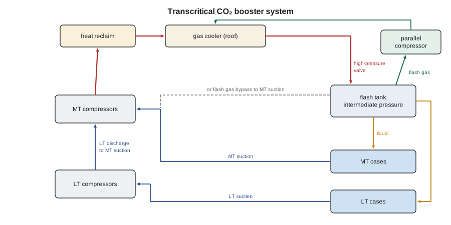
A transcritical booster system has two compressor groups, as a two-stage ammonia plant does, but arranged differently. Low-temperature compressors take vapour from the freezer evaporators, at about −30 °C (−22 °F) saturation, and discharge it directly into the suction of the medium-temperature compressors. The medium-temperature compressors take that vapour, together with the vapour from the medium-temperature evaporators at about −8 °C (18 °F), and compress it to the high side. That is the booster arrangement, and it lets one rack serve both loads with a single refrigerant and no cascade heat exchanger.
On the high side, the hot gas goes to the gas cooler on the roof. In cool weather, the gas cooler works as a condenser, because the outdoor air is cold enough to condense carbon dioxide below its critical point. In warm weather, it cannot condense, so it cools a supercritical fluid instead. Either way, the refrigerant then passes through a high-pressure valve, which controls the pressure in the gas cooler, and expands into a flash tank, also called the receiver, at an intermediate pressure, typically about 35 bar (500 psig). In the flash tank, the refrigerant separates into liquid, which feeds the evaporators through their expansion valves, and flash gas, the vapour formed in the expansion.
The flash gas must be removed to keep the receiver's pressure steady. In the simplest systems it goes through a flash gas bypass valve, which throttles it down to the medium-temperature suction, where the medium-temperature compressors compress it again from the lower pressure. In systems with parallel compression, a separate compressor takes the flash gas directly from the receiver at its higher pressure and compresses it to the high side, which takes much less work. Some systems add ejectors, which use the energy of the high-pressure flow to lift part of the vapour from the evaporators to the receiver's pressure, further reducing the compressor work.
Why hot weather hurts
The efficiency of a carbon dioxide system depends strongly on the temperature of the refrigerant leaving the gas cooler. In cool weather, the gas cooler produces subcooled liquid at a modest pressure, little of it flashes in the expansion, and the system is very efficient, often more efficient than an HFC system. In hot weather, the gas cooler's outlet is a warm supercritical fluid at a high pressure. When it expands into the flash tank, a large fraction of it, sometimes nearly half, flashes to vapour, which does no useful cooling and must be compressed again. The compressors also work across a much higher pressure ratio. The script uses approximate values read from a carbon dioxide property chart to compare the medium-temperature side of Harvest Lane's system on a winter day and a hot day, with flash gas bypass and with parallel compression.
# Transcritical CO2 booster, medium-temperature side: flash gas and parallel compression (illustrative chart values)
h_l, h_v = 200.0, 430.0           # kJ/kg, liquid and vapour in the flash tank at about 35 bar
h_evap_out = 433.0                # kJ/kg leaving the MT evaporators
load = 85.0                       # kW medium-temperature load
cases = {  # gas cooler exit enthalpy, MT compressor and parallel compressor work per kg (actual)
    "winter, subcritical 50 bar": (230.0, 38.0, 20.0),
    "hot day, transcritical 90 bar": (300.0, 75.0, 45.0)}
for name, (h_gc, w_mt, w_par) in cases.items():
    x = (h_gc - h_l) / (h_v - h_l)            # flash gas fraction
    m_liq = load / (h_evap_out - h_l)         # kg/s of liquid to the cases
    m_tot = m_liq / (1 - x)
    bypass = m_tot * w_mt                     # flash gas throttled to MT suction
    parallel = m_liq * w_mt + (m_tot - m_liq) * w_par
    print(f"{name}: flash gas {x:.0%}")
    print(f"   flash gas bypass:     {bypass:5.1f} kW, COP {load / bypass:.2f}")
    print(f"   parallel compression: {parallel:5.1f} kW, COP {load / parallel:.2f} ({1 - parallel / bypass:.0%} less power)")
for t in (30, 33, 36):
    print(f"gas cooler exit {t} C -> rule-of-thumb optimum pressure about {2.6 * t + 7.5:.0f} bar")
hot_hours = 380                           # hours a year above about 27 C outdoors in Kitchener (illustrative)
saved = hot_hours * (48.4 - 40.0) + (8760 - hot_hours) * (15.9 - 15.0)
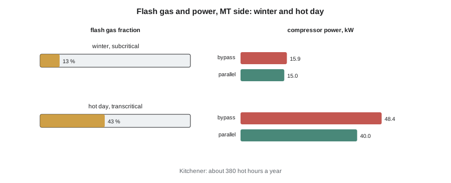
print(f"Kitchener: about {hot_hours} hot hours; parallel compression saves about {saved:,.0f} kWh a year on the MT side")winter, subcritical 50 bar: flash gas 13% flash gas bypass: 15.9 kW, COP 5.33 parallel compression: 15.0 kW, COP 5.68 (6% less power) hot day, transcritical 90 bar: flash gas 43% flash gas bypass: 48.4 kW, COP 1.76 parallel compression: 40.0 kW, COP 2.13 (17% less power) gas cooler exit 30 C -> rule-of-thumb optimum pressure about 86 bar gas cooler exit 33 C -> rule-of-thumb optimum pressure about 93 bar gas cooler exit 36 C -> rule-of-thumb optimum pressure about 101 bar Kitchener: about 380 hot hours; parallel compression saves about 10,734 kWh a year on the MT side
On a winter day, with the gas cooler condensing at about 50 bar, only about 13 % of the refrigerant flashed, and the medium-temperature side ran at a COP of about 5.3. On a hot day, with the gas cooler at about 90 bar, about 43 % flashed, and the COP fell to about 1.8 with flash gas bypass. Parallel compression raised it to about 2.1, saving about 17 % of the power on the hot day but only about 6 % in winter. Kitchener has only a few hundred hot hours a year, so the annual saving from parallel compression on the medium-temperature side was modest, about 10,700 kWh. The figures come from a simplified model, but the pattern is real, and it is why the climate shapes the design of every carbon dioxide system.
Controlling the gas cooler pressure
In subcritical operation, the condensing pressure follows the condensing temperature, as in any refrigeration system. In transcritical operation, pressure and temperature are independent, and the controller must choose the pressure. Raising the gas cooler pressure at a given outlet temperature lowers the outlet enthalpy and the flash fraction, increasing the cooling per kilogram, but it also increases the compressor work. There is an optimum pressure that gives the best COP, and it rises with the gas cooler's outlet temperature. A rule of thumb from the research literature puts the optimum at roughly 2.6 bar for each degree Celsius of gas cooler outlet temperature, plus about 7.5 bar, which gives about 93 bar at a 33 °C outlet. Rack controllers apply a curve of this kind, set by the manufacturer, through the high-pressure valve, and a technician should not override it.
The gas cooler fans, usually with variable speed, try to bring the outlet temperature as close to the outdoor air temperature as possible, because every degree of approach lost costs efficiency. Adiabatic gas coolers, which wet pads in front of the coils to cool the air by evaporation on hot days, can lower the outlet temperature by several degrees and are common in warmer climates. For Kitchener, Nadia specified a dry gas cooler with oversized coils.
Heat reclaim
Carbon dioxide's high discharge temperatures, often 70 to 100 °C (160 to 210 °F), make it very good at heat recovery. A heat reclaim exchanger before the gas cooler transfers heat from the discharge gas to a water and glycol loop that heats the store's air handlers, its domestic hot water and sometimes the floor under the freezer. In winter, the controller can raise the gas cooler pressure above what refrigeration alone would need, to make more heat available at a useful temperature, effectively running the rack as a heat pump. For a grocery in a cold climate, recovered heat can supply much of the store's heating. At Harvest Lane 2, the heat reclaim was expected to supply most of the store's space heating from October to April, replacing natural gas.
Controls and safety features
A carbon dioxide rack is controlled by a dedicated rack controller that manages the compressors, the high-pressure valve, the flash gas bypass valve, the parallel compressor, the gas cooler fans, heat reclaim and the safety functions, and communicates with the case controllers and the store's monitoring system. The main safety features are:
- High-pressure safety controls and relief valves on each pressure level, set below the design pressures: high side, receiver, medium-temperature suction and low-temperature suction.
- A standby condensing unit, usually a small HFC or propane unit, on emergency power, that keeps the receiver cold and its pressure within limits during a power failure.
- Leak detection in the machine room and in walk-in coolers and freezers, with alarms and ventilation.
- Oil management: carbon dioxide compressors use oils, typically polyalkylene glycol or polyol ester types, that are soluble in carbon dioxide, so oil returns with the refrigerant, but booster systems still use oil separators and oil level management on each compressor group.
- Pressure-rated service valves, sight glasses and connections, all marked for carbon dioxide.
Start-up and service
Harvest Lane 2's start-up followed the manufacturer's procedure closely. After the pressure test with nitrogen at the specified test pressures for each pressure level and a deep triple evacuation, the system was charged first with carbon dioxide vapour to well above the triple point, then with liquid into the receiver, by weight, to the designer's charge, about 350 kg (770 lb). The standby unit was started and tested, then the medium-temperature compressors, then the low-temperature ones, one group at a time, with the controller's settings checked against the design. Theo's job was to log the pressures at every level, the gas cooler outlet temperature and the flash tank level, and to confirm that the case controllers were bringing each case down at the expected rate, as he had done at the first store in RAC-310.
Service work on carbon dioxide racks uses the same principles as other refrigeration work, with three extra rules that Nadia drilled into everyone. Know the pressure of every part before you open anything, and expect it to be higher than you think. Never trap liquid in a section of pipe, because its pressure can rise beyond the pipe's rating within minutes. And watch the air you breathe: work in the machine room and in walk-ins with a carbon dioxide detector running and the ventilation on.
| Feature | What it does | When it matters most |
|---|---|---|
| Flash gas bypass | Throttles flash gas to MT suction | Simple systems; cool climates |
| Parallel compression | Compresses flash gas from receiver pressure | Warm weather; high flash gas |
| Ejectors | Use high-pressure flow energy to lift vapour | Warm climates; large systems |
| Adiabatic gas cooler | Cools inlet air by evaporation | Hot, dry weather |
| Heat reclaim | Heats the store and water from discharge gas | Cold climates; winter |
| Standby condensing unit | Holds receiver pressure in a power failure | Every system |
Common mistakes
MistakeOverriding the high-pressure valve to lower the gas cooler pressure on a hot day.
InsteadThe controller seeks the optimum pressure; lowering it raises the flash gas and can reduce capacity.
MistakeAssuming a carbon dioxide rack will perform the same in every climate.
InsteadHot hours drive the design: parallel compression, ejectors and adiabatic gas coolers help in warm climates.
MistakeTreating the standby condensing unit as optional.
InsteadIt keeps the receiver within its design pressure when the rack stops.
MistakeCharging liquid into an evacuated system to save time.
InsteadCharge vapour first, above the triple point, then liquid by weight.
MistakeWorking in a walk-in during a leak search without a carbon dioxide detector.
InsteadCarry a detector and run the ventilation.
Summary and key terms
- In a booster system, low-temperature compressors discharge into the medium-temperature suction, and one rack serves both loads.
- The gas cooler condenses in cool weather and cools a supercritical fluid in warm weather; a high-pressure valve controls its pressure.
- In hot weather a large share of the refrigerant flashes in the receiver, cutting efficiency; parallel compression and ejectors reduce the penalty.
- The optimum gas cooler pressure rises with the gas cooler outlet temperature; controllers apply it.
- High discharge temperatures make heat reclaim very effective in cold climates.
- Standby cooling, pressure relief at each level, leak detection and rated components are essential.
- Booster system
- A CO₂ system in which low-temperature compressors discharge into the medium-temperature suction.
- Gas cooler
- The heat exchanger that rejects heat from CO₂, as a condenser in cool weather and as a cooler of supercritical fluid in warm weather.
- High-pressure valve
- The valve that controls the gas cooler pressure and expands the refrigerant into the flash tank.
- Flash gas
- Vapour formed when refrigerant expands into the receiver.
- Parallel compression
- Compressing flash gas directly from the receiver pressure with a separate compressor.
- Ejector
- A device that uses the energy of a high-pressure flow to raise the pressure of a low-pressure vapour.
Practice problems
Work each problem on paper first, then reveal the answer to check.
Gas cooler outlet enthalpy is 280 kJ/kg, and the flash tank liquid and vapour enthalpies are 200 and 430. What is the flash gas fraction?
Show answer
(280 − 200) ÷ 230 = about 35 %.
Using the rule of thumb, what is the optimum gas cooler pressure at a 35 °C outlet?
Show answer
2.6 × 35 + 7.5 = about 98 bar.
Why does parallel compression save more energy in hot weather?
Show answer
More flash gas forms, and compressing it from receiver pressure takes less work than from suction pressure.
Why does a carbon dioxide rack need a standby condensing unit?
Show answer
To keep the receiver cold and within its design pressure during a power failure or shutdown.
Lesson quiz · 5 questions
Score 60% or more to complete this lesson.
Create a free account to save your progress, take quizzes and earn a certificate.