
RAC-410 · Lesson 9 of 12 · 16 min
Chiller plant controls and sequencing
Theo's answer to Raj's question in lesson 2 had been that CH-2, the variable-speed centrifugal, was the most efficient machine in the plant at part load. In lesson 2 he had also found that the operators still ran CH-1 first, out of habit. In September, with the low delta-T repairs under way and Anika from the controls contractor on site to reprogram the plant, Grace asked Raj and Theo to help write a new sequence of operation. "I want the plant to choose the right machines by itself," she said, "and I want my operators to understand why it chose them."
This lesson covers how a chiller plant is controlled: the controls on each chiller and the plant-level sequence that decides which chillers, pumps and tower cells run, when to stage them, and what setpoints to use. It also covers chilled-water and condenser-water reset and the idea of optimizing the plant as a whole.
Two layers of control
Each chiller has its own control panel, supplied by the manufacturer, which runs the machine safely and holds its leaving chilled-water setpoint. It controls the compressor's capacity, the vanes, slide valve or speed, the oil system and the metering device; it monitors safeties such as low evaporator pressure and temperature, high condenser pressure, motor current and temperature, oil pressure and surge; and it limits the machine's demand and loading rate. It usually communicates with the building automation system over BACnet or Modbus, which RAC-230 lesson 10 described, reporting its status, alarms and many internal readings, and accepting a start command, a setpoint and a demand limit.
The plant controller, part of the building automation system or a dedicated plant control system, coordinates the machines. It decides how many chillers to run and which ones, starts and stops pumps and tower cells in the right order, resets setpoints and handles failures. The chiller's own safeties always remain in charge of protecting the chiller; the plant controller tells it what to do, not how to protect itself.
Starting and stopping a chiller
A chiller cannot simply be switched on. A typical start sequence for a water-cooled chiller in a primary-secondary plant is:
- Open the chiller's isolation valves, if motorized, and start its primary chilled-water pump and condenser water pump.
- Prove flow through both heat exchangers with flow switches or differential pressure across the barrels; the chiller will not start without it.
- Make sure a tower cell is available and the condenser water is within the chiller's allowed start-up range, using the tower bypass if it is too cold.
- Enable the chiller, which runs its own pre-start checks, such as oil pressure and temperature, and starts the compressor, loading it gradually to avoid a demand spike and pulling down the water temperature.
Stopping reverses the order, with the pumps running for a few minutes after the compressor stops so that the evaporator does not freeze or the condenser pressure spike. Each step has a timer and a proof, and a failure at any step moves to the next available chiller and raises an alarm.
Staging chillers on and off
The heart of the sequence is deciding when to add or drop a chiller. A plant adds a chiller when the running machines cannot hold the supply temperature, or are near their capacity, and drops one when the remaining machines could carry the load comfortably. Common staging signals are:
- Load. The plant calculates the load from flow and delta-T and compares it with the running chillers' capacity: add a chiller when the load exceeds, for example, 90 % of running capacity for some minutes; drop one when the load would be under about 80 % of the remaining machines' capacity.
- Supply temperature. Add a chiller when the supply water rises above setpoint for some minutes, which shows the running machines are at their limit.
- Chiller loading. Use each chiller's reported percent load or motor current.
- Flow. In primary-secondary plants, add a chiller when there is reverse flow in the decoupler, as lesson 7 described, which is exactly how low delta-T forced Riverbend's second chiller on.
Staging needs delays and dead bands so that chillers do not cycle on and off near a threshold; a chiller has a minimum run time and a limit on starts per hour to protect its motor. The order in which machines are staged also matters a great deal when they are different, as at Riverbend.
The order of the machines
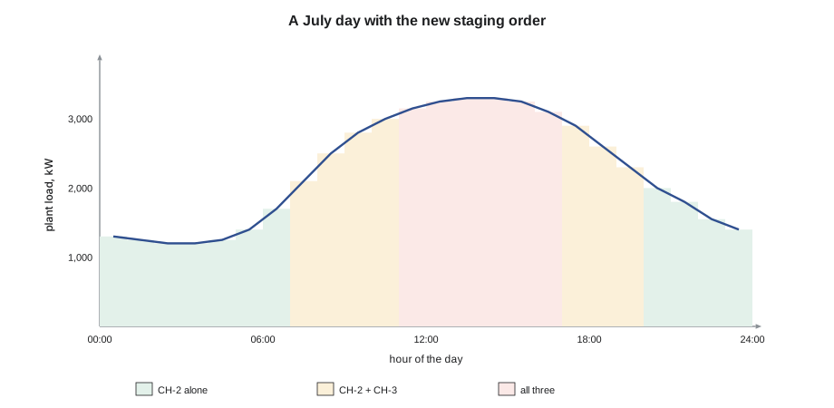
Riverbend's old sequence ran CH-1 first, added CH-3 next and CH-2 last. Theo proposed the reverse for most of the year: CH-2 first, because its variable-speed drive made it the most efficient machine at part load; CH-3 second, to add moderate capacity; and CH-1 last, for the peak, where its constant-speed efficiency was close to its best. The script simulates a July day with the plant's hourly loads, simple part-load curves fitted to each chiller's submittal points from lesson 2, and equal loading of the running chillers, for both orders.
# A July day at Riverbend: two ways of staging the same three chillers (load in kW, kW input per kW of cooling)
loads = [1300, 1250, 1200, 1200, 1250, 1400, 1700, 2100, 2500, 2800, 3000, 3150,
         3250, 3300, 3300, 3250, 3100, 2900, 2600, 2300, 2000, 1800, 1550, 1400]
cap = {"CH-1": 2110, "CH-2": 2110, "CH-3": 1055}
def eff(ch, frac):                             # simple part-load curves fitted to the submittal points
    if ch == "CH-1": return 0.165 + 0.10 * (1 - frac) ** 2 - 0.02 * (1 - frac)
    if ch == "CH-2": return 0.159 - 0.14 * (1 - frac) + 0.12 * (1 - frac) ** 2
    return 0.176 - 0.06 * (1 - frac) + 0.05 * (1 - frac) ** 2
def run(order, max_load=0.95):
    kwh = 0.0
    for q in loads:
        on = []
        for ch in order:                       # add machines in order until they can carry the load
            on.append(ch)
            if q <= max_load * sum(cap[c] for c in on): break
        share = q / sum(cap[c] for c in on)    # equal percentage loading
        kwh += sum(cap[c] * share * eff(c, share) for c in on)
    return kwh
a = run(["CH-1", "CH-3", "CH-2"])
b = run(["CH-2", "CH-3", "CH-1"])
print(f"old order (CH-1 lead): {a:,.0f} kWh of chiller electricity for the day")
print(f"new order (CH-2 lead): {b:,.0f} kWh, saving {a - b:,.0f} kWh ({1 - b / a:.0%})")
print(f"cooling delivered {sum(loads):,} kWh; average COP {sum(loads) / a:.2f} -> {sum(loads) / b:.2f}")old order (CH-1 lead): 8,643 kWh of chiller electricity for the day new order (CH-2 lead): 7,718 kWh, saving 925 kWh (11%) cooling delivered 53,600 kWh; average COP 6.20 -> 6.94
Over the day, the new order used about 7,700 kWh of chiller electricity against about 8,600 for the old, a saving of about 11 %, and raised the average chiller COP from about 6.2 to 6.9, with the same cooling delivered. Over a year, with many more mild days on which CH-2 could run alone, the saving would be larger in proportion. The model is simplified; it ignores the pumps and towers that each chiller brings with it and assumes the same condenser water for both orders. But it shows clearly that the order matters.
Two practical points shaped the final sequence. First, running hours: always leading with one machine wears it out faster and leaves the others sitting, which some owners prefer to balance by rotation. Riverbend chose efficiency, with a monthly check that the lag machines were run and tested. Second, reliability: the operating rooms could not lose chilled water, so the sequence kept a fast-start standby and ensured that a failed chiller was replaced by the next one within minutes. On emergency power, only CH-2 and its pumps could run, and the sequence had a separate mode for that.
Chilled-water supply reset
Raising the chilled-water supply temperature lowers the chillers' lift and saves energy, about 2 to 3 % per kelvin (1 to 1.5 % per °F) in rough terms. But warmer water makes the coils draw more flow, so the pumps work harder, and it reduces dehumidification, which matters in hospitals. Plants usually reset the supply temperature from the coil valve positions: if no coil valve is nearly fully open, the supply can be raised a little; if several are, it is lowered. Riverbend's sequence allowed reset from 6.7 to 8.5 °C (44 to 47 °F) in mild weather, but not for the operating room air handlers, which had their own humidity control and could call the supply back down. In winter the supply rose to 10 °C (50 °F) for free cooling, as lesson 5 described.
Condenser water reset and optimization
Lesson 5 described the tower's setpoint strategies. The plant sequence ties them to the chillers: colder condenser water lowers chiller power but raises tower fan power, and there is an optimum in between that depends on the load, the wet bulb and the equipment. Simple plants reset the condenser water with the wet bulb plus a fixed approach, within the chillers' limits. More advanced plants calculate the setpoint that minimizes total chiller, tower and pump power, using performance curves from the manufacturers and the plant's own measured data. Some go further and optimize the whole plant, choosing which chillers to run, the chilled-water and condenser-water setpoints and the pump speeds together, every few minutes. These optimizers can save a great deal, but they depend on good sensors and calibrated meters, and they need someone who understands them to keep them working.
Anika added a wet-bulb reset with a 3 K (5 °F) approach at part load, a minimum of 18 °C (65 °F) to the chillers in summer, and a separate low limit for start-ups. Together with the staging change, it was expected to save more than the staging alone; lesson 12 brings the numbers together.
Sensors, trends and alarms
A plant sequence is only as good as its sensors. Chilled-water supply and return temperatures, flow meters, differential pressure sensors, outdoor wet bulb, tower water temperatures and each chiller's reported data must be accurate, because the sequence uses them to decide what to run. A return temperature sensor reading 0.5 K (1 °F) low can make the load calculation wrong by a tenth at a typical delta-T. Riverbend's commissioning of the new sequence, which RAC-230 lesson 11 would recognize, included checking every sensor against a calibrated instrument, trending the plant for two weeks and comparing the results with the model.
The sequence also defined alarms with priorities: loss of chilled-water supply temperature, a chiller failure, a pump failure, a refrigerant monitor alarm and a tower basin low level were critical and paged the operators; a rising condenser approach, a purge running more than usual or a decoupler in reverse flow for more than an hour were maintenance alarms for the next working day. Grace's operators got a one-page description of the sequence, in plain language, posted in the control room.
When the sequence fails
A sequence must also say what happens when equipment does not behave. If a chiller fails to start, the plant should try the next one and alarm; if a pump fails to prove flow, its standby should start; if communication with a chiller is lost, the plant should treat it as unavailable rather than guess. On loss of power, the plant must restart in an orderly way when power returns, not start every machine at once. At Riverbend, the new sequence's failure modes were tested one by one during commissioning, by switching off a pump, disconnecting a flow switch and stopping a chiller at its panel, while the operators watched what the plant did. Two of the tests found problems that would otherwise have shown up during a real failure on a hot afternoon.
Common mistakes
MistakeLeading with the same chiller for years out of habit.
InsteadChoose the order by part-load efficiency and conditions, and review it when equipment changes.
MistakeStaging chillers on decoupler flow without checking delta-T.
InsteadFix the coil problems that cause low delta-T; staging only responds to them.
MistakeResetting chilled water upward without watching humidity and pump energy.
InsteadReset from coil valve positions, with limits for critical areas.
MistakeTrusting a plant optimizer with uncalibrated sensors.
InsteadCalibrate sensors and meters and verify with trends.
MistakeLetting the plant controller override chiller safeties.
InsteadThe chiller's own controls always protect the chiller.
Summary and key terms
- Each chiller's own panel controls and protects it; the plant controller decides which machines run and at what setpoints.
- Starting a chiller requires proven chilled-water and condenser water flow, an available tower and suitable condenser water.
- Chillers are staged on load, supply temperature, loading or decoupler flow, with delays and minimum run times.
- Staging order matters when machines differ; variable-speed chillers usually lead at part load.
- Chilled-water reset lowers lift but raises pump flow and reduces dehumidification; condenser water reset or optimization balances chiller and tower energy.
- Accurate sensors, trends and well-designed alarms make a sequence work.
- Sequence of operation
- A written description of how a system’s equipment is started, staged, controlled and protected.
- Staging
- Adding or removing chillers, pumps or tower cells as the load changes.
- Lead chiller
- The chiller started first when cooling is needed.
- Demand limit
- A cap on a chiller’s electrical load set by the controls.
- Chilled-water reset
- Raising or lowering the supply temperature with load or valve positions.
- Condenser water reset
- Lowering the condenser water setpoint when outdoor conditions allow.
- Plant optimization
- Choosing equipment and setpoints to minimize total plant energy.
- Flow proof
- A confirmation, from a switch or sensor, that water is flowing.
Practice problems
Work each problem on paper first, then reveal the answer to check.
Why must a chiller's pumps run before its compressor starts?
Show answer
The chiller needs proven flow through both heat exchangers to start safely.
A plant has two equal chillers: one constant speed, one variable speed. Which should lead at part load, and why?
Show answer
The variable-speed chiller, because its part-load efficiency is much better.
What are two drawbacks of raising the chilled-water supply temperature?
Show answer
More coil flow and pump energy, and less dehumidification.
Name two alarms that should page an operator immediately in a hospital plant.
Show answer
Any two of: loss of supply temperature, chiller failure, pump failure, refrigerant monitor alarm, tower basin low level.
Lesson quiz · 5 questions
Score 60% or more to complete this lesson.
Create a free account to save your progress, take quizzes and earn a certificate.