
RAC-130 · Lesson 8 of 12 · 22 min
Single-phase motors and capacitors
Priya's text arrived at six in the morning: the walk-in cooler was at 9 °C (48 °F) and climbing, and the condensing unit outside was humming but not running. Dana and Theo were there by seven. With her ear near the unit, Dana heard the compressor try to start, hum for a few seconds and click off. "Locked rotor, then overload," she said. With the power locked out, she discharged and removed the run capacitor, a 35-microfarad, 370-volt unit, and measured it: 27.9 microfarads, about 20 per cent low. She measured the compressor windings, C to R 1.1 ohms, C to S 2.8 ohms, S to R 3.9 ohms, and from each terminal to the shell, no continuity. The compressor was sound. A new capacitor and a hard-start kit had the cooler running within the hour.
Single-phase motors run almost every small fan, blower and compressor in residential and light commercial equipment. This lesson explains how they start and run, the main motor types, how compressor terminals are identified, the start relays and capacitors that help them start, and how to test capacitors and windings, including the running capacitance check.
Why single-phase motors need help to start
An AC induction motor works by setting up a magnetic field in its stationary part, the stator, that pulls a rotor around. A three-phase supply naturally creates a field that rotates, because its three currents peak one after another. A single-phase supply creates a field that only pulses back and forth along one line. It can keep a rotor turning once it is moving, but it gives no push in either direction from a standstill. A single-phase motor with only one winding would simply hum.
Single-phase motors solve this with a second winding, the start or auxiliary winding, placed in the stator at a different position from the main or run winding. If the current in the start winding can be made to peak at a different moment from the current in the run winding, the two windings together produce a field that rotates, at least roughly, and the motor starts in a definite direction. The motor types differ in how they create that difference, called phase shift, and whether they keep the start winding in the circuit after starting.
The speed of an induction motor is set by the supply frequency and the number of magnetic poles in the stator. The synchronous speed is 120 times the frequency divided by the number of poles: 3,600 rpm for a two-pole motor and 1,800 rpm for a four-pole motor on 60 hertz. The rotor runs a little slower than the field, a difference called slip, so a four-pole motor's nameplate typically reads about 1,725 rpm and a six-pole motor about 1,075 rpm.
The main types
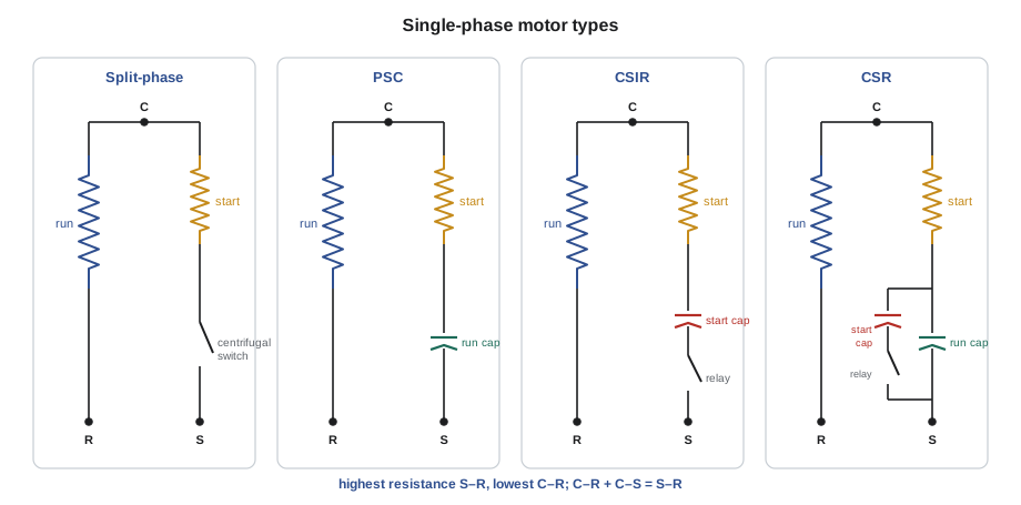
- Shaded-pole motors use a copper ring around part of each stator pole to delay the field in that part and give a weak rotation. They are simple and cheap but inefficient and have very little starting torque, so they are used for small fans such as some evaporator fans and older condenser fans.
- Split-phase motors make the start winding of finer wire with more resistance, so its current is shifted from the run winding's. A centrifugal switch or electronic switch disconnects the start winding at about three quarters of full speed, because it would overheat if left in. They have moderate starting torque.
- Permanent split capacitor (PSC) motors connect a run capacitor in series with the start winding, which shifts its current strongly, and leave both permanently in the circuit. They are efficient and quiet but have low starting torque. Condenser fan motors, many blower motors and most residential compressors are PSC motors. Low starting torque is acceptable for compressors in systems with fixed metering devices, where pressures equalize during the off cycle.
- Capacitor start, induction run (CSIR) motors connect a start capacitor in series with the start winding for starting only. A start relay removes it once the motor is up to speed. They have high starting torque.
- Capacitor start, capacitor run (CSR) motors combine both: a start capacitor and a run capacitor are in parallel during starting, giving high starting torque, and the start capacitor is removed by a relay once running, leaving the run capacitor for efficient operation. Commercial refrigeration compressors on systems with thermostatic expansion valves, which do not equalize pressures during the off cycle, often need this extra starting torque.
A hard-start kit, as Dana installed at the brewery, adds a start capacitor and a potential relay or a solid-state switch to a PSC compressor, turning it temporarily into a CSR compressor during each start. It helps a compressor that struggles to start against unequal pressures, on low voltage or with age. It does not cure a compressor that is mechanically locked or has a shorted winding.
Compressor terminals: common, start and run
A single-phase hermetic compressor has three terminals: common (C), start (S) and run (R). The run winding is connected between C and R and the start winding between C and S. The two windings meet at C. The run winding has heavier wire and lower resistance; the start winding has finer wire and higher resistance. That gives a simple rule for identifying the terminals when the markings are missing or the wiring has been changed:
- Measure resistance between each pair of terminals with the power off and the wires removed.
- The highest reading is between S and R, through both windings in series, so the remaining terminal is C.
- The lowest reading is between C and R, the run winding.
- The middle reading is between C and S, the start winding.
- The two smaller readings should add up to the largest: C–R plus C–S equals S–R.
The test also finds faults. An open winding reads OL on one or two pairs. A shorted winding reads much lower than normal, which needs the manufacturer's values for comparison. Any measurable resistance from a terminal to the copper suction line or the shell indicates a winding grounded to the shell; that compressor must not be restarted. A grounded compressor is confirmed with a megohmmeter, as Lesson 5 described.
# Identify C, S and R from three resistance readings between terminals 1, 2 and 3
readings = {(1, 2): 3.9, (1, 3): 1.1, (2, 3): 2.8}      # ohms, power off, wires removed
(sr_pair, sr) = max(readings.items(), key=lambda kv: kv[1])
common = ({1, 2, 3} - set(sr_pair)).pop()
others = {pair: r for pair, r in readings.items() if pair != sr_pair}
(cr_pair, cr) = min(others.items(), key=lambda kv: kv[1])
(cs_pair, cs) = max(others.items(), key=lambda kv: kv[1])
run = (set(cr_pair) - {common}).pop()
start = (set(cs_pair) - {common}).pop()
print(f"C = terminal {common}, R = terminal {run}, S = terminal {start}")
print(f"run winding {cr} ohms, start winding {cs} ohms, S-R {sr} ohms")
print("check C-R + C-S = S-R:", round(cr + cs, 2), "vs", sr,
"-> ok" if abs(cr + cs - sr) < 0.1 * sr else "-> recheck readings")C = terminal 3, R = terminal 1, S = terminal 2 run winding 1.1 ohms, start winding 2.8 ohms, S-R 3.9 ohms check C-R + C-S = S-R: 3.9 vs 3.9 -> ok
With the brewery compressor's readings, the code identifies the terminals and confirms that the windings add up, which is what Dana found by hand.
Start relays
Motors with start capacitors or with split-phase starting need something to remove the start components once the motor is running. Several kinds of start relay are used:
- A potential relay, also called a voltage relay, has its coil connected across the start winding, from S to C, and a set of normally closed contacts in series with the start capacitor. As the motor speeds up, the voltage generated across the start winding, called back EMF, rises above the supply voltage. At its pick-up voltage the relay coil pulls its contacts open, removing the start capacitor. Potential relays are used on larger compressors and on hard-start kits; they must be matched to the compressor.
- A current relay has its coil in series with the run winding and a set of normally open contacts in series with the start winding or start capacitor. The high starting current pulls the contacts closed; as the motor speeds up and the current falls, they drop open. Current relays are used on small refrigeration compressors, such as household refrigerators, and must be mounted upright because they rely partly on gravity.
- A PTC relay, or positive temperature coefficient thermistor, is a ceramic device whose resistance is low when cool and rises sharply as it heats. In series with the start winding, it lets starting current flow and then, as it heats within a second or two, effectively disconnects the start winding. It must cool for several minutes before the next start, which is why some small compressors cannot restart immediately after stopping.
- Electronic start devices, often in hard-start kits, use timing and solid-state switches to do the same job.
Capacitors
A capacitor stores charge between conducting plates separated by an insulator. Its capacitance, in microfarads (µF), describes how much charge it stores per volt. Motor capacitors come in two kinds, which must never be confused:
| Run capacitor | Start capacitor | |
|---|---|---|
| Construction | Metallized polypropylene film, usually oil-filled metal can | Electrolytic, usually in a black plastic case |
| Duty | Continuous: in the circuit whenever the motor runs | Intermittent: a few seconds per start only |
| Typical values | About 3 to 80 µF | About 80 to 800 µF, often a range such as 88–108 µF |
| Typical voltage ratings | 370 or 440 VAC | About 125 to 330 VAC |
| Tolerance | Commonly about ±5 or ±6 % | Wide, often given as a range |
| Usual failure | Gradual loss of µF; bulged top | Burns open or shorts if left in the circuit too long |
A dual run capacitor combines two capacitors in one can with three terminals: C (common), HERM (to the compressor's start terminal) and FAN (to the fan motor's start winding). It might be rated 35 + 5 µF, 370 VAC. When replacing a capacitor, match the microfarad value and use a voltage rating equal to or higher than the original: a 440-volt capacitor can replace a 370-volt one of the same µF, but not the other way round. Start capacitors often have a bleed resistor across their terminals to discharge them between starts, and most run capacitors have a safety feature that disconnects them internally if pressure builds up, which is why a failing one may bulge on top.
A run capacitor that has lost capacitance reduces the phase shift in the start winding, which lowers starting torque, raises current and temperature in the windings, and reduces efficiency. A compressor with a weak capacitor may start on a mild day and fail to start on a hot one, as the brewery's did. A shorted capacitor puts the start winding directly across the line and can damage it quickly.
Testing capacitors
With the power locked out, discharge the capacitor through a resistor and remove at least one wire. Inspect it for bulging, leaks and damaged terminals. Measure the capacitance with the meter's capacitance function and compare with the rating and tolerance. Also check from each terminal to the metal can; any continuity means the capacitor must be replaced.
A capacitor can also be checked while the motor runs, which tests it under real voltage and temperature. In a PSC circuit, the capacitor carries the start-winding current, and the voltage across it is the capacitor voltage. On 60-hertz power the capacitance is:
where I is the current in amperes on the start-winding wire from the capacitor and V is the voltage measured across the capacitor's two terminals, HERM to C or FAN to C. The voltage across a run capacitor is often higher than the supply voltage, sometimes 300 to 400 volts on a 240-volt system, because of the voltage generated in the start winding, which is one reason the capacitor's voltage rating matters. This measurement is made live, inside the restricted approach boundary, so it needs the full PPE and planning described in Lesson 1, with the clamp placed around the start wire before the unit is started.
# Running capacitance check: microfarads = 2652 x start-winding amps / capacitor volts
def mfd(amps, volts):
    return 2652 * amps / volts

checks = [  # (description, rated uF, start-winding amps, capacitor volts)
    ("brewery compressor, old capacitor", 35.0, 3.9, 370.0),
    ("brewery compressor, new capacitor", 35.0, 4.9, 372.0),
    ("brewery condenser fan",              5.0, 0.78, 410.0),
]
tol = 0.06
for name, rated, a, v in checks:
    c = mfd(a, v)
    dev = (c - rated) / rated
    verdict = "within tolerance" if abs(dev) <= tol else "replace"
print(f"{name:36s}: {c:5.1f} uF vs {rated:4.1f} uF rated ({dev:+.0%}) -> {verdict}")brewery compressor, old capacitor : 28.0 uF vs 35.0 uF rated (-20%) -> replace brewery compressor, new capacitor : 34.9 uF vs 35.0 uF rated (-0%) -> within tolerance brewery condenser fan : 5.0 uF vs 5.0 uF rated (+1%) -> within tolerance
The running check confirms what the bench test found, and shows that the new capacitor and the fan capacitor are within the usual tolerance of about 6 per cent. The constant 2652 applies only to 60-hertz power.
Worked problem
Is the capacitor the problem?
A condenser fan motor turns slowly and runs hot. Its capacitor is rated 7.5 µF ±6 %. Running, the start-winding current is 0.62 A and the capacitor voltage is 352 V. Find the running capacitance and decide.
Show solution
- \[C = \frac{2652 \times 0.62}{352} \approx 4.7\ \mu\text{F}\]
- \[\frac{4.7 - 7.5}{7.5} \approx -37\ \%, \quad \text{far outside } \pm 6\ \%\]
Answer: The capacitor has lost more than a third of its capacitance, which explains the slow, hot fan. Replace it with a 7.5 µF capacitor of the same or higher voltage rating, then check the motor's current against its nameplate; a motor that has run hot for a long time may also be damaged.
Testing single-phase motors
A motor that will not start or runs badly is tested in order: supply voltage at the motor terminals while it tries to run, the capacitor, the start relay if there is one, the winding resistances, the windings to ground, and finally the mechanical condition. For fan motors, spin the blade or wheel by hand with the power locked out: it should turn freely without grinding or tight spots. A compressor that hums and trips with good voltage, a good capacitor, good windings and a working start relay may be mechanically locked; a hard-start kit may free a stuck compressor once, but a compressor that needs repeated help is near the end of its life.
Common mistakes
MistakeReplacing a 440-volt run capacitor with a 370-volt one.
InsteadUse an equal or higher voltage rating and the same µF value.
MistakeUsing a start capacitor as a run capacitor.
InsteadStart capacitors are short-duty; left in the circuit they fail within seconds to minutes.
MistakeIdentifying compressor terminals by the position of the pins.
InsteadMeasure resistance: the highest is S–R, the lowest C–R.
MistakeRestarting a compressor with a terminal shorted to the shell.
InsteadAny continuity to ground condemns it; confirm with a megohmmeter.
MistakeMeasuring the running capacitance current on the wrong wire.
InsteadClamp the wire from the capacitor to the start winding and measure voltage across the capacitor.
Summary and key terms
- Single-phase motors need a start winding with a phase-shifted current to create a rotating field.
- Shaded-pole, split-phase, PSC, CSIR and CSR motors differ in starting method and torque.
- Compressor terminals: highest resistance S–R, lowest C–R, middle C–S, and C–R + C–S = S–R.
- Potential, current and PTC relays remove start components once the motor is running.
- Run capacitors are continuous duty, start capacitors short duty; replace with the same µF and equal or higher voltage.
- Running capacitance in µF = 2652 × start-winding amps ÷ capacitor volts on 60 Hz.
- Run winding
- The main winding of a single-phase motor, between C and R.
- Start winding
- The auxiliary winding that creates the phase shift for starting, between C and S.
- PSC motor
- A permanent split capacitor motor with a run capacitor always in the start winding circuit.
- CSR motor
- A capacitor start, capacitor run motor with both start and run capacitors.
- Potential relay
- A start relay whose coil senses start-winding voltage and opens to remove a start capacitor.
- PTC relay
- A thermistor that removes the start winding by rising in resistance as it heats.
- Run capacitor
- A continuous-duty capacitor that stays in a motor circuit while it runs.
- Start capacitor
- A short-duty electrolytic capacitor used only during starting.
- Hard-start kit
- An add-on start capacitor and relay that increases a compressor's starting torque.
- Synchronous speed
- The speed of a motor's rotating field, 120 f ÷ P.
Practice problems
Work each problem on paper first, then reveal the answer to check.
Readings between three compressor terminals are 0.9, 3.4 and 2.5 ohms. Which reading is C–S?
Show answer
2.5 ohms; 0.9 is C–R and 3.4 is S–R.
What is the synchronous speed of a six-pole motor on 60 Hz?
Show answer
120 × 60 ÷ 6 = 1,200 rpm.
A dual capacitor is rated 40 + 5 µF. Which terminal connects to the compressor?
Show answer
HERM, with C as the common.
Start-winding current 4.2 A and capacitor voltage 380 V. What is the capacitance?
Show answer
2652 × 4.2 ÷ 380 ≈ 29.3 µF.
Lesson quiz · 5 questions
Score 60% or more to complete this lesson.
Create a free account to save your progress, take quizzes and earn a certificate.