
RAC-130 · Lesson 11 of 12 · 21 min
Thermostats and basic control sequences
In late October a homeowner called Northfield in a mild panic: her new smart thermostat said "heating", the outdoor heat pump was running, and the house was getting colder. She had installed the thermostat herself the weekend before, moving each wire from the old thermostat to the terminal with the same letter. Theo found the problem in the thermostat's installer settings. The old thermostat had used an O terminal, and the new one had been left at its factory setting for a B system. The reversing valve was being energized in heating instead of in cooling, so the heat pump was cooling the house while the thermostat called for heat. One menu change later, warm air was coming out of the registers.
This lesson explains what thermostats do and how the basic control sequences of air conditioners, furnaces and heat pumps work. It covers thermostat types and sensors, the standard terminal letters, cooling and heating sequences, heat pump reversing valve control, auxiliary and emergency heat, an introduction to defrost, and how to check a thermostat and its wiring. Controls are covered in depth in RAC-230; this lesson gives the foundation.
What a thermostat does
A thermostat compares the temperature it senses with a set point and switches equipment on or off to hold the temperature close to it. It has three parts: a sensor, a way of comparing the sensed temperature with the set point, and switches that connect the 24-volt R terminal to the terminals that call for fan, cooling or heating. Whatever its age or price, every conventional thermostat is, electrically, a set of switches between R and the other terminals.
Older mechanical thermostats use a bimetal strip or coil, two metals bonded together that expand at different rates, so the strip bends as temperature changes and opens or closes a contact. Many older units used a glass bulb of mercury tilted by the bimetal coil to make or break the circuit. A mercury thermostat removed from service must not go in the garbage; it should go to a thermostat recycling program, which wholesalers and municipalities run in both countries. Mechanical heating thermostats often had a heat anticipator, a small adjustable heater that warmed the bimetal slightly during a heating call so that the thermostat would switch off a little before the room reached the set point; it had to be set to the current of the heating circuit, which technicians measured with the ten-wrap method from Lesson 5.
Electronic thermostats sense temperature with a thermistor, a resistor whose resistance changes with temperature. Most are NTC thermistors, negative temperature coefficient, whose resistance falls as temperature rises; a common type reads about 10 kΩ at 25 °C (77 °F). A microprocessor reads the sensor, applies the set point and a programmed control method, and switches the outputs with small relays or solid-state switches. Programmable thermostats change set points by schedule; smart thermostats add Wi-Fi, remote control and learning features; communicating thermostats exchange data with matching equipment over a two- or four-wire data connection rather than switching individual terminals.
Terminal letters
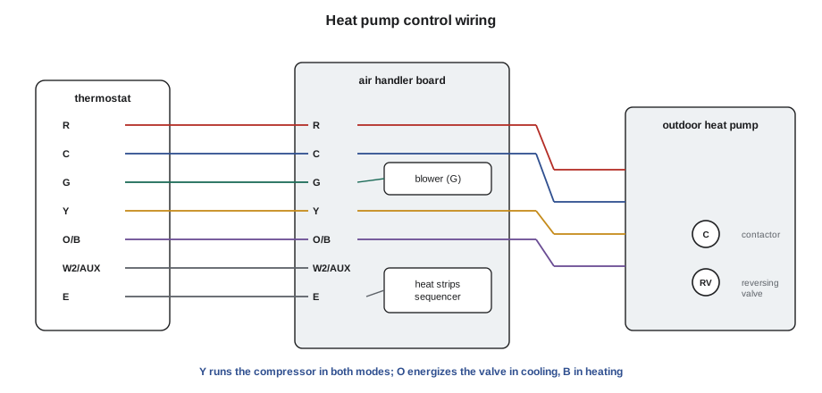
The terminal letters are an industry convention. Manufacturers use them consistently enough that a technician can usually read an unfamiliar thermostat, but always check the installation instructions for the equipment and the thermostat.
| Terminal | Usual function |
|---|---|
| R, Rh, Rc | 24-volt hot from the transformer. Rh and Rc are separate heating and cooling transformers on some systems, joined by a jumper when there is one transformer |
| C | Transformer common, giving continuous power to an electronic thermostat |
| G | Indoor fan |
| Y, Y1, Y2 | Cooling, or compressor; Y2 is the second stage of a two-stage compressor |
| W, W1, W2 | Heating; on a heat pump W or W2 is usually auxiliary (electric) heat |
| O, B | Reversing valve: O energized in cooling, B energized in heating |
| E, EM | Emergency heat: heat from the auxiliary source only, compressor locked out |
| AUX | Auxiliary heat on some heat pump thermostats |
| L | A fault or service indicator signal from the equipment |
| S1, S2 | Remote or outdoor temperature sensor |
Colour codes for thermostat cable are a habit, not a rule: R is usually red, C blue or black, G green, Y yellow, W white and O/B orange or dark blue. In practice, previous installers use whatever colours were spare, and the only reliable way to know is to trace each wire to the equipment end.
Cooling sequence for a split system
When the thermostat calls for cooling, it closes R to Y and R to G. The G signal energizes the indoor blower relay, or tells an ECM blower to run at cooling speed. The Y signal goes to the outdoor unit, through any safety controls and time delays, to the contactor coil, which starts the compressor and condenser fan. When the thermostat is satisfied, it opens both. Many control boards keep the blower running for a short time after the compressor stops to recover the cooling left in the coil, and many add a delay before the compressor can restart.
Two-stage and variable-capacity systems add more signals: Y1 for low stage, Y2 for high stage, or a communicating signal that sets the exact capacity. A two-stage thermostat calls Y2 when Y1 cannot keep up, for example when the temperature falls more than a set amount behind the set point or after a set time.
Heating sequence for a gas furnace
On a call for heat, the thermostat closes R to W. A modern furnace's control board then runs an ignition sequence, checking its safety switches at each step:
- It checks that the high-limit switch is closed and that the pressure switch is open, proving that the switch is not stuck.
- It starts the inducer, or draft fan, which pulls combustion products through the heat exchanger. The pressure switch closes, proving the vent is clear.
- After a pre-purge, it energizes the igniter, usually a hot surface igniter that glows to ignition temperature in several seconds.
- It opens the gas valve. The burners light, and the board proves flame through the flame sensor, using a small DC current of a few microamperes that flows only when flame is present; if flame is not proven within a few seconds, the board closes the gas valve and retries or locks out.
- After a heat-on delay, so that the heat exchanger warms up first, it starts the blower at heating speed.
- When the thermostat is satisfied, the gas valve closes, the inducer runs a post-purge, and the blower runs on for a heat-off delay before stopping.
Furnace boards flash an LED code to report faults such as an open pressure switch, a flame failure or an open limit, with the code list printed inside the door. Servicing the gas train itself, such as the gas valve, burners and venting, is gas work that in Ontario requires a gas technician certificate under the Technical Standards and Safety Authority (TSSA), and many refrigeration mechanics hold one as well.
Heat pump sequences
A heat pump uses a reversing valve to run its refrigeration cycle in either direction: in cooling, the indoor coil is the evaporator; in heating, the indoor coil becomes the condenser and the outdoor coil the evaporator. The reversing valve has a solenoid coil, usually 24 volts, that shifts it from one position to the other. The compressor runs on Y in both modes; the thermostat's O or B terminal decides which way the valve is set:
- O systems energize the reversing valve in cooling. With the coil de-energized, the valve rests in heating. Most manufacturers use O.
- B systems energize the reversing valve in heating, and the valve rests in cooling. Some manufacturers have traditionally used B.
A thermostat set for the wrong one runs the valve backwards in every mode: cooling when heat is called for and heating when cooling is called for, the fault in Theo's call. Smart and digital thermostats have an installer setting for O or B, and some equipment boards accept either.
Because a heat pump's output falls as outdoor temperature drops, most heat pumps in cold climates have auxiliary heat, usually electric heat strips in the air handler, or are paired with a gas furnace in a dual-fuel system. The thermostat brings on auxiliary heat, through W2 or AUX, when the heat pump cannot keep up, for example when the room falls a degree or two below the set point. Emergency heat, selected manually at the thermostat, locks out the compressor and runs only the auxiliary heat, for use when the heat pump has failed. A thermostat left on emergency heat by mistake is a common cause of very high winter electricity bills.
# Thermostat outputs for a heat pump: which terminals are energized?
def outputs(mode, need, valve="O"):
    # mode: "cool", "heat", "emergency"; need: 0 = satisfied, 1 = stage 1, 2 = needs aux
    out = set()
    if need == 0:
        return out
    out |= {"G"}
    if mode == "cool":
        out |= {"Y"}
        if valve == "O":
            out |= {"O"}
    elif mode == "heat":
        out |= {"Y"}
        if valve == "B":
            out |= {"B"}
        if need >= 2:
            out |= {"W2/AUX"}
    elif mode == "emergency":
        out |= {"W2/AUX", "E"}           # compressor locked out
    return out

for valve in ("O", "B"):
    for mode, need in (("cool", 1), ("heat", 1), ("heat", 2), ("emergency", 1)):
print(f"{valve} system, {mode:9s} stage {need}: {sorted(outputs(mode, need, valve))}")O system, cool stage 1: ['G', 'O', 'Y'] O system, heat stage 1: ['G', 'Y'] O system, heat stage 2: ['G', 'W2/AUX', 'Y'] O system, emergency stage 1: ['E', 'G', 'W2/AUX'] B system, cool stage 1: ['G', 'Y'] B system, heat stage 1: ['B', 'G', 'Y'] B system, heat stage 2: ['B', 'G', 'W2/AUX', 'Y'] B system, emergency stage 1: ['E', 'G', 'W2/AUX']
The table produced by the code is a useful checklist. In an O system the O terminal is energized only in cooling; in a B system B is energized only in heating. In every mode except emergency heat, Y runs the compressor.
Defrost: an introduction
In heating, the outdoor coil of a heat pump runs colder than the outdoor air, often below freezing, and moisture in the air freezes on its fins. Frost blocks airflow and lowers the heat pump's output, so the unit must periodically defrost. A defrost control board on the outdoor unit decides when, using a coil temperature sensor and either a timer or a demand method that looks at the temperature difference between the coil and the outdoor air. During defrost the board switches the reversing valve to cooling, which sends hot gas to the outdoor coil, stops the outdoor fan so the heat goes into the frost, and usually brings on auxiliary heat to keep the air in the house from going cold. Defrost ends when the coil sensor reaches its termination temperature or after a maximum time, typically about ten minutes.
Defrost explains several things homeowners notice: steam rising from the outdoor unit, a whooshing sound as the valve shifts, and a few minutes of cooler air from the registers. Faults in the defrost sensor, the board or the reversing valve produce units that ice up solid or defrost far too often. Defrost controls are covered fully in RAC-230 and the heat pump course.
Checking a thermostat and its wiring
Many no-heat and no-cool calls are thermostat or wiring problems, and a few simple checks separate the thermostat from the equipment:
- Check the thermostat's settings, mode, schedule and installer configuration first, including O or B, the equipment type and the number of stages.
- Measure 24 volts between R and C at the thermostat sub-base. If it is missing, the problem is the transformer, its fuse or the wiring, as Lesson 6 described.
- With the thermostat calling, measure from C to each output terminal that should be energized. If R to C is present but the output is missing, the thermostat is not switching.
- To test the equipment without the thermostat, remove the thermostat from its base and briefly jumper R to the terminal to be tested, such as R to G for the fan or R to Y for cooling. If the equipment responds, the equipment and wiring are good and the thermostat or its configuration is the problem. Never jumper R to C, which shorts the transformer.
- At the equipment end, measure from C to each incoming thermostat wire to confirm the signal arrives.
Location matters too. A thermostat on an outside wall, near a supply register, in sunlight, above a lamp or beside a kitchen will sense a temperature that does not represent the house, and the equipment will short-cycle or run too long. Holes behind the thermostat where the cable enters the wall should be sealed so that cold or warm air from inside the wall does not blow across the sensor.
Worked problem
Is the thermostat switching?
On a no-cooling call at a heat pump, a technician measures at the thermostat with it calling for cooling: R to C 26.1 V, C to G 26.0 V, C to Y 0 V, C to O 26.0 V. At the outdoor unit, C to Y 0 V. What should the technician conclude?
Show solution
- \[V_{R\text{–}C} = 26.1\ \text{V} \Rightarrow \text{power present}\]
- \[V_{C\text{–}G} \approx V_{C\text{–}O} \approx 26\ \text{V}, \quad V_{C\text{–}Y} = 0\ \text{V at the thermostat}\]
Answer: The thermostat has power and is switching G and O, but not Y. Either its Y output has failed or it is holding off the compressor, for example on its own anti-short-cycle delay or a lockout setting. Waiting five minutes and rechecking, then jumpering R to Y at the sub-base, will show which. The equipment and outdoor wiring have not yet been tested.
Common mistakes
MistakeMoving wires to matching letters on a new thermostat without checking its configuration.
InsteadSet the system type, stages and O or B in the installer menu.
MistakeJumpering R to C to test equipment.
InsteadThat shorts the transformer; jumper R to the terminal being tested.
MistakeThrowing a mercury thermostat in the garbage.
InsteadTake it to a thermostat recycling program.
MistakeAssuming wire colours match their terminals.
InsteadTrace each wire to the equipment end.
MistakeTreating a heat pump that steams and goes quiet for a few minutes as a fault.
InsteadThat is a normal defrost cycle; check frequency and duration against the board's settings.
Summary and key terms
- A thermostat is a set of switches from R to G, Y, W and O/B, controlled by a sensor and set point.
- Electronic thermostats use thermistors; smart and communicating thermostats need correct configuration.
- Cooling: R to Y and G starts the compressor and blower; boards add delays and staging.
- Gas furnaces run a proven ignition sequence: inducer, pressure switch, igniter, gas valve, flame proof, blower delay.
- Heat pumps run the compressor on Y in both modes; O energizes the reversing valve in cooling, B in heating.
- Auxiliary heat supplements the heat pump; emergency heat locks out the compressor; defrost reverses the cycle briefly to clear the outdoor coil.
- Set point
- The temperature the thermostat is set to hold.
- Thermistor
- A resistor whose resistance changes with temperature, used as a sensor.
- Heat anticipator
- A small heater in an older thermostat that ends heating calls slightly early.
- Reversing valve
- A valve that switches a heat pump between heating and cooling.
- O terminal
- The reversing valve terminal energized in cooling.
- B terminal
- The reversing valve terminal energized in heating.
- Auxiliary heat
- Supplementary heat, usually electric strips, that helps a heat pump in cold weather.
- Emergency heat
- A mode that locks out the compressor and heats with the auxiliary source only.
- Defrost
- A cycle that reverses a heat pump briefly to melt frost from the outdoor coil.
- Flame sensor
- A rod that proves burner flame by a small DC current through the flame.
Practice problems
Work each problem on paper first, then reveal the answer to check.
Which terminal runs the compressor on a heat pump in both heating and cooling?
Show answer
Y.
A B system's thermostat is set for O. What happens on a call for heat?
Show answer
The valve is not energized, so a B system stays in cooling and the house cools.
How do you test whether the equipment responds without the thermostat?
Show answer
Remove the thermostat and briefly jumper R to the terminal to be tested, never R to C.
What three things happen during a typical heat pump defrost?
Show answer
The reversing valve shifts to cooling, the outdoor fan stops and auxiliary heat comes on.
Lesson quiz · 5 questions
Score 60% or more to complete this lesson.
Create a free account to save your progress, take quizzes and earn a certificate.