
RAC-130 · Lesson 5 of 12 · 22 min
Meters and safe measurement
Theo's tool list from the union hall had said "multimeter", and he had bought an inexpensive one from a hardware store. Dana turned it over in her hand, read the small print beside the input jacks and handed it back. "Keep it for the truck radio," she said. "It's rated CAT II 300 volts. The disconnect on a rooftop unit is a CAT III location, and the residence runs at 600 volts. If this meter sees a voltage spike while you're holding it on a live circuit, it can explode in your hands." She lent him one of the shop's clamp meters until his first paycheque, and spent the afternoon teaching him how to use it.
Meters are the technician's eyes in electrical work. This lesson covers the digital multimeter and clamp meter, measurement categories and why they matter, how to measure voltage, current, resistance, continuity and capacitance safely and correctly, insulation resistance testing with a megohmmeter, and how to read meter accuracy and avoid the common errors that lead to wrong diagnoses.
The tools
A digital multimeter, DMM, measures voltage, resistance and usually current, capacitance, frequency and temperature, selected with a rotary switch. A clamp meter combines a multimeter with jaws that close around a conductor to measure current without breaking the circuit; for HVAC-R service it is usually the main meter, because measuring the current of motors and compressors is part of almost every call. Other tools include a two-pole voltage tester, a solenoid or electronic tester with two probes that shows voltage without a rotary switch to set wrongly; a non-contact voltage detector; a megohmmeter for insulation testing; and a phase rotation meter for three-phase equipment.
The meter for HVAC-R work should be true RMS, so that it reads correctly on the distorted waveforms near drives and electronic loads; should have a low-impedance voltage mode, often marked LoZ, to avoid ghost readings; should measure capacitance in microfarads and temperature; and, above all, should have a measurement category and voltage rating for the highest-energy circuit it will be used on.
Measurement categories
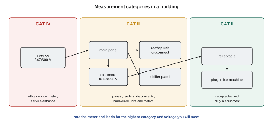
Electrical systems carry brief voltage spikes, called transients, caused by lightning, utility switching and motors being switched off. A spike of several thousand volts lasting microseconds can trigger an arc inside a meter whose insulation and spacings are inadequate, and the system's energy then feeds the arc. The international safety standard for meters, IEC 61010-1, adopted in Canada as CSA C22.2 No. 61010-1 and in the United States as UL 61010-1, defines measurement categories according to how much energy is available where the meter is used:
- CAT IV: the origin of the installation, such as the utility service drop, the electrical meter base and the service entrance equipment, and outdoor conductors.
- CAT III: the building's distribution system, such as panels, feeders, disconnect switches, and permanently connected equipment like condensing units, rooftop units, motors and chillers.
- CAT II: equipment plugged into receptacles, such as a window air conditioner, a plug-in ice machine or a portable dehumidifier, and the receptacles themselves at a distance from the panel.
A meter's rating is given as a category with a voltage, such as CAT III 1000 V or CAT IV 600 V. Both parts matter: a CAT III 600 V meter is suitable for a 240-volt condensing unit disconnect, but not for a 600-volt chiller panel if transients there could exceed what it was tested for. The rule is to choose a meter rated for the highest category and voltage you will meet. Test leads, probes and clamps have their own ratings; the lowest-rated part of the set limits the whole set. Leads should have finger guards and shrouded connectors, and many rules for CAT III and IV locations call for probe tips with no more than about 4 mm (5/32 in) of exposed metal, to reduce the chance of bridging two terminals.
For Northfield's work, which includes 600-volt equipment at the residence, the shop standard is a clamp meter and leads rated at least CAT III 1000 V and CAT IV 600 V.
Measuring voltage
Voltage is measured in parallel: the two leads touch the two points between which the voltage is wanted, while the circuit stays connected. The steps are the same each time:
- Inspect the meter and leads for cracks, worn insulation and damage. Check that the black lead is in COM and the red lead in the V jack, not in an amperes jack.
- Select AC or DC volts. On autoranging meters the range is chosen automatically.
- Prove the meter on a known live source, or on a proving unit that generates a test voltage.
- Connect the black lead first, to the reference point such as ground, neutral or the C terminal, then the red lead. Keep one hand clear where practical, and keep your fingers behind the guards.
- Read and record the value with its unit. Remove the red lead first.
Two problems cause many wrong readings. A high-impedance digital meter can show a phantom or ghost voltage on a disconnected wire that runs beside live wires, because capacitive coupling induces a small voltage that the meter's high input impedance does not load down. The reading may be tens of volts on a wire that cannot actually deliver current. Switching to the meter's low-impedance mode loads the circuit enough to make a ghost voltage collapse, while a real source holds up. The second problem is the opposite: a high-resistance connection, such as a burnt contact, may show full voltage when measured with a meter, which draws almost no current, but collapse when the load tries to draw its current. Voltage measured with the load running is the real test.
Ghost voltage and poor connections are why measurements are always made with the circuit in a known state: power off and locked out for resistance, power on and the load trying to run for voltage drop, and live-dead-live for proving absence of voltage.
Measuring current
Current is measured in series: all the current must pass through the meter or, with a clamp meter, the jaws must surround the conductor carrying it. A clamp meter senses the magnetic field around the conductor, so it measures without breaking the circuit and without touching live metal. Clamp only one conductor at a time. If the jaws surround both the supply and return conductors of the same circuit, their magnetic fields cancel and the reading is near zero, however much current flows.
Most clamp meters have an inrush or maximum function that captures the high starting current of a motor in the first fraction of a second, useful for seeing whether a compressor's locked-rotor current is reached and how quickly it falls as the compressor comes up to speed. For very small currents, such as the 24-volt current drawn by a gas valve or thermostat, wrapping the wire through the jaws several times multiplies the reading: ten turns of wire carrying 0.4 amperes show 4.0 amperes, which is then divided by ten.
Many multimeters also measure current directly through their test leads, with the red lead moved to an A or mA jack. This puts the meter in series with the circuit, and it is the connection most likely to cause an accident: if the meter is left on an amperes jack and the leads are then placed across a voltage source, the meter becomes a short circuit. The internal fuse is designed to clear that fault safely only if it is the correct high-energy fuse. HVAC-R technicians use the series current jacks only for small DC currents such as the microampere flame-sensor signal of a furnace, and use the clamp for everything else.
The reading is compared with the nameplate. Motors and compressors list rated load amperes (RLA) or full load amperes (FLA), and locked-rotor amperes (LRA). A compressor running at 60 per cent of its RLA may be short of refrigerant or have a mechanical problem; one running above its RLA is overloaded by high head pressure, low voltage or internal wear.
Measuring resistance and continuity
Resistance is measured with the power off and locked out, capacitors discharged, and the component isolated from the rest of the circuit. Isolation matters because the ohmmeter measures everything connected between its leads; a coil measured while still wired into a circuit may read the coil in parallel with a transformer winding or another load. Lift at least one wire from the component before measuring it.
Continuity mode beeps when the resistance between the leads is below a low threshold, a quick way to check fuses, switches, wires and contacts. An open circuit shows OL, for overload or out of limit, meaning the resistance is too high to measure. Resistance readings are used to check heater elements, contactor and relay coils, motor windings, thermistors and the condition of switches and contacts. A closed switch should read close to zero ohms; a contactor coil typically reads tens of ohms; motor windings read from a fraction of an ohm for a large compressor to tens of ohms for a small fan motor.
Measuring capacitance
In capacitance mode the meter charges and discharges the capacitor to measure its value in microfarads. The capacitor must be discharged and disconnected from the circuit first. Compare the reading with the value printed on the capacitor; run capacitors are commonly rated within about plus or minus 5 or 6 per cent, and one reading outside its tolerance band should be replaced. Because a capacitor can test correctly on a meter's low test voltage and still fail under full voltage and heat, Lesson 8 also shows how to calculate its value while the motor runs.
Insulation resistance and the megohmmeter
Winding insulation keeps current inside the copper. As insulation ages, overheats or is attacked by moisture and acid, its resistance to ground falls. A normal ohmmeter, using a few volts, cannot detect weakened insulation that would still break down under the stress of operating voltage. A megohmmeter applies a high DC test voltage, typically 500 or 1,000 volts for HVAC-R equipment, between the windings and ground, and measures the very small leakage current to give insulation resistance in megohms.
The test is done with the equipment locked out and disconnected from its supply, with electronic boards, drives and capacitors disconnected so that the test voltage cannot damage them, and with the windings discharged afterwards because the insulation stores charge. A compressor should never be tested while it is under a deep vacuum, because insulation is much weaker in a vacuum and can be damaged by the test. Liquid refrigerant mixed with the oil can make a healthy compressor read low, so readings are most useful when taken after the compressor has run and warmed, with crankcase heat on.
Acceptable values depend on the equipment and the manufacturer's guidance. A common field guideline treats readings above about 100 megohms as healthy and readings falling to a few megohms as a sign of deteriorating insulation, but a single reading is less useful than a trend. Insulation resistance falls as temperature rises, roughly halving for each 10 °C (18 °F) increase, so readings should be corrected to a standard temperature before they are compared from one visit to the next.
# Insulation resistance trend for the residence's chiller compressor
# Correct each reading to a 40 C base: resistance roughly halves per 10 C rise
readings = [  # (visit, megohms, winding temperature C)
    ("2024 spring", 1450, 30),
    ("2025 spring",  980, 35),
    ("2026 spring",  420, 38),
    ("2026 autumn",  160, 45),
]
base = 40
for visit, mohm, t in readings:
    corrected = mohm * 2 ** ((t - base) / 10)
    flag = "watch" if corrected < 200 else "ok"
print(f"{visit}: {mohm:5d} megohms at {t} C -> {corrected:6.0f} at {base} C {flag}")2024 spring: 1450 megohms at 30 C -> 725 at 40 C ok 2025 spring: 980 megohms at 35 C -> 693 at 40 C ok 2026 spring: 420 megohms at 38 C -> 366 at 40 C ok 2026 autumn: 160 megohms at 45 C -> 226 at 40 C ok
The trend tells a clearer story than any single reading. Corrected to the same temperature, the chiller compressor's insulation has fallen by a large factor in two years. Raj's recommendation was an oil and acid test and a closer look at the motor's operating temperature, before the insulation reaches the point of failure.
Accuracy and resolution
Meter specifications give accuracy as a percentage of the reading plus a number of counts, or digits, in the last place shown. A meter specified at ±(1.0 % + 3 counts) on a range with a resolution of 0.1 volt could be off by 1 per cent of the reading plus 0.3 volts. Accuracy is worse on capacitance and current ranges than on DC voltage, and clamp readings depend on the conductor being centred in the jaws.
Worked problem
What a reading can tell you
A clamp meter specified at ±(2.0 % + 5 counts) with 0.1 A resolution reads 14.6 A on a compressor whose RLA is 15.0 A. Is the compressor definitely running below its RLA?
Show solution
- \[\text{uncertainty} = 0.02 \times 14.6 + 5 \times 0.1 = 0.29 + 0.5 \approx 0.8\ \text{A}\]
- \[14.6 \pm 0.8\ \text{A} \;\Rightarrow\; 13.8\ \text{to}\ 15.4\ \text{A}\]
Answer: No. The true current could be anywhere from about 13.8 to 15.4 A, which includes the RLA. The reading says the compressor is close to its rated load, not that it is safely below it. Small differences between readings should not drive a diagnosis; large differences and trends should.
| Measurement | Power | How connected | Key precaution |
|---|---|---|---|
| AC or DC voltage | On | In parallel, across two points | Category rating; leads in V and COM; prove the meter |
| Current (clamp) | On | Jaws around one conductor | Only one conductor in the jaws |
| Current (in series) | On | Meter inserted in the circuit | Small DC currents only; correct fuse |
| Resistance, continuity | Off, locked out | Across the isolated component | Discharge capacitors; lift a wire |
| Capacitance | Off, locked out | Across the disconnected capacitor | Discharge first |
| Insulation resistance | Off, disconnected | Between winding and ground | Disconnect electronics; no deep vacuum; discharge after |
Common mistakes
MistakeUsing a CAT II meter on a condensing unit disconnect.
InsteadUse a meter and leads rated CAT III, or CAT IV at the service, for the system voltage.
MistakeLeaving the red lead in the amperes jack and then measuring voltage.
InsteadCheck lead positions before every voltage test; use the clamp for current.
MistakeClamping around a whole cable or both conductors of a circuit.
InsteadClamp one conductor; the fields of supply and return conductors cancel.
MistakeMeasuring a coil's resistance while it is still wired into the circuit.
InsteadLift a wire so parallel paths do not change the reading.
MistakeCondemning a wire because a high-impedance meter shows 40 volts on it.
InsteadCheck for ghost voltage in low-impedance mode.
MistakeMegohm-testing a compressor that is under vacuum or connected to its drive.
InsteadTest only with the system out of vacuum and electronics disconnected.
Summary and key terms
- Clamp meters are the HVAC-R technician's main meter; choose true RMS, LoZ mode, capacitance and temperature.
- CAT IV is at the service, CAT III at panels and hard-wired equipment, CAT II at plug-in loads; rate meter and leads for the highest category and voltage.
- Voltage is measured in parallel, current in series or with a clamp around one conductor.
- Resistance, continuity and capacitance are measured with power off, capacitors discharged and the part isolated.
- Megohmmeters test insulation at high DC voltage; correct for temperature and watch the trend.
- Every reading has an uncertainty; compare with the nameplate and with expected values.
- Digital multimeter
- A meter that measures voltage, resistance and other quantities, selected by a switch.
- Clamp meter
- A meter that measures current by sensing the magnetic field around a conductor.
- Measurement category
- A rating (CAT II, III, IV) for the transient energy a meter can withstand at a location.
- True RMS
- A meter that measures the correct effective value of distorted waveforms.
- Ghost voltage
- A false voltage reading caused by capacitive coupling on an unloaded conductor.
- LoZ mode
- A low-impedance voltage mode that makes ghost voltages collapse.
- Inrush current
- The high current drawn briefly when a motor or coil is energized.
- Megohmmeter
- An insulation tester that applies a high DC voltage and reads resistance in megohms.
- RLA
- Rated load amperes, the compressor current used for design and protection.
Practice problems
Work each problem on paper first, then reveal the answer to check.
Which measurement category applies at a rooftop unit's disconnect?
Show answer
CAT III, for permanently connected equipment and distribution.
Ten turns of a thermostat wire through the jaws show 3.5 A. What is the actual current?
Show answer
0.35 A.
Why lift a wire before measuring a component's resistance?
Show answer
To isolate it from parallel paths that would change the reading.
Why are megohm readings corrected for temperature?
Show answer
Insulation resistance falls as temperature rises, so uncorrected readings from different visits cannot be compared.
Lesson quiz · 5 questions
Score 60% or more to complete this lesson.
Create a free account to save your progress, take quizzes and earn a certificate.