
RAC-130 · Lesson 6 of 12 · 20 min
Transformers and 24-volt control circuits
The call came in on the first hot weekend of June: a house in the Westmount area of Kitchener, no cooling, and no heat the evening before when the homeowner had tried the furnace fan to move some air. The thermostat screen was blank. Theo checked the batteries, which were fine, and then followed Dana to the basement. She removed the furnace door, held the door switch in with a piece of tape the way the manufacturer's service instructions allow, and measured 120 volts at the transformer's primary and 0 volts at its secondary. A small automotive-style fuse on the control board had blown. "Now the question isn't what failed," she said. "It's why it failed. Fuses don't blow by themselves." Outside, they found the thermostat cable to the condenser rubbed through where it crossed the edge of the cabinet. The bare Y conductor had touched the metal every time the unit vibrated.
This lesson explains the 24-volt control circuits that run almost every HVAC-R system. It covers how transformers work, primary and secondary windings and voltage taps, transformer ratings in VA, Class 2 circuits, how the control circuit connects the thermostat to the equipment, sizing a control transformer, testing transformers and control wiring, and the faults that blow control fuses.
Electromagnetism and induction
Current in a wire creates a magnetic field around it. Winding the wire into a coil concentrates the field, and wrapping the coil around an iron core concentrates it further, making an electromagnet. This is how contactor and relay coils pull their contacts closed and how solenoid valves open. The reverse effect is just as important: a changing magnetic field through a coil induces a voltage in it. Because AC current rises, falls and reverses 120 times a second, the magnetic field it creates is always changing, and so it can induce a voltage in a second coil placed on the same iron core. That is the principle of the transformer.
How a transformer works
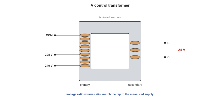
A transformer has two windings on a shared laminated iron core. The primary winding is connected to the supply. Its alternating current creates an alternating magnetic field in the core, and the field induces a voltage in the secondary winding, which supplies the load. There is no electrical connection between the windings, only a magnetic one, so a transformer also isolates the control circuit from the line-voltage supply.
The voltages are in proportion to the number of turns of wire on each winding:
A transformer with ten times as many turns on its primary as on its secondary steps 240 volts down to 24 volts. Because a transformer is very efficient, the power out is almost equal to the power in, so the current is stepped up by the same ratio that the voltage is stepped down: a secondary delivering 1 ampere at 24 volts draws only about 0.1 ampere at 240 volts on the primary. Transformers work only on AC; connected to DC, there is no changing field, the primary acts as a plain low-resistance coil, and it overheats and burns out.
Control transformers in HVAC-R equipment are step-down transformers. Furnaces and air handlers usually have a 120-volt primary; condensing units, packaged units and commercial equipment often have a multi-tap primary with taps for 208 and 240 volts, or for higher voltages on 600-volt equipment. The tap must match the actual supply. A transformer wired on the 240-volt tap but supplied at 208 volts delivers only about 21 volts, which can make contactors chatter and electronic controls misbehave; one wired on the 208-volt tap but supplied at 240 volts delivers about 28 volts, which shortens the life of coils and controls.
VA ratings and Class 2 circuits
Transformers are rated in volt-amperes, VA: the product of secondary voltage and the current the transformer can supply continuously without overheating. The common residential control transformer is 40 VA, which at 24 volts allows about 1.7 amperes. Commercial equipment uses 50, 75 or 100 VA transformers, or larger.
Most residential and light commercial thermostat wiring is a Class 2 circuit, a category defined in the Canadian Electrical Code for circuits whose power is limited so that they present little risk of fire or shock. For a 24-volt circuit, a Class 2 source is limited to 100 VA, either by its own design, an inherently limited transformer, or by a fuse or breaker. Class 2 transformers are marked as such. Because the power is limited, Class 2 wiring may use thermostat cable without conduit in most locations, but it must be kept separate from line-voltage conductors unless separated by a barrier or suitable insulation.
The low voltage and limited power make Class 2 circuits much safer to work on than line-voltage circuits, but not harmless. A short circuit on a 40 VA transformer can still overheat thin wire, and the control board's fuse, usually rated 3 or 5 amperes, is there to protect the transformer and the board. Many furnace boards also ground the C side of the secondary to the chassis, so any bare conductor touching the cabinet is a short to C.
The basic control circuit
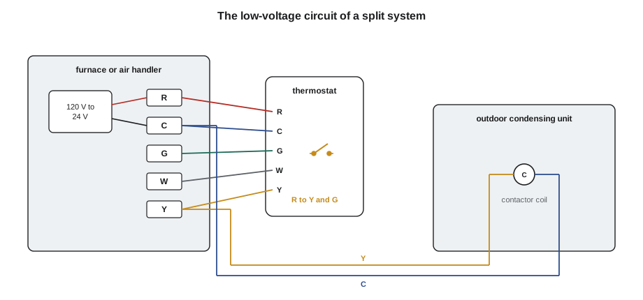
In a typical split system, the transformer is in the furnace or air handler. Its secondary terminals are labelled R, for the 24-volt hot side, and C, for common. The thermostat is a set of switches that connect R to the other terminals:
- R to G: energizes the indoor blower relay, running the fan.
- R to Y: energizes the outdoor unit's contactor coil, wired from Y to C through a two-conductor cable, starting the compressor and condenser fan.
- R to W: calls for heat from the furnace's heating controls.
A thermostat with a display or Wi-Fi needs continuous power, which it gets from a C wire back to the transformer common. Older thermostats used batteries or drew a trickle of power through the equipment's loads. Lesson 11 covers thermostats and the terminals of heat pumps.
The outdoor unit itself usually has no transformer: its contactor coil is powered from the indoor transformer through the thermostat cable. That cable runs outdoors, often along a wall and into the condenser's cabinet, where vibration, sharp edges, lawn trimmers and animals can damage it. A shorted Y conductor at the condenser connects R to C through only the wire's resistance as soon as the thermostat calls for cooling, and the fuse blows. If the short is to the cabinet and the C side is grounded, the result is the same.
Sizing a control transformer
When accessories are added, such as a humidifier, zone dampers, an electronic air cleaner or a second-stage relay, the load on the transformer rises. The VA drawn by each device appears on its label or in its instructions. Coils have two values: a high inrush VA for the instant they pull in, while the magnetic gap is open, and a much lower sealed or holding VA once closed. A transformer should be sized for the sealed load with a margin, and checked so that the inrush of coils that pull in together does not pull the voltage too low.
# Control transformer sizing: add sealed VA, check inrush, pick a standard size
loads = {   # device: (sealed VA, inrush VA)
    "thermostat (powered)":       (3,  3),
    "outdoor contactor coil":     (7, 40),
    "indoor blower relay":        (4, 15),
    "gas valve":                  (12, 12),
    "humidifier solenoid":        (8, 20),
    "zone damper (each of 2)":    (7, 7),
}
counts = {"zone damper (each of 2)": 2}
sealed = sum(v[0] * counts.get(k, 1) for k, v in loads.items())
inrush = sum(v[1] * counts.get(k, 1) for k, v in loads.items())
print(f"total sealed load: {sealed} VA, all coils pulling in together: {inrush} VA")
need = sealed * 1.25                       # 25 % margin on the steady load
size = next(s for s in (40, 50, 75, 100) if s >= need)
print(f"with 25 % margin: {need:.0f} VA -> choose a {size} VA transformer")
print(f"secondary current at 24 V: {sealed / 24:.2f} A steady, {inrush / 24:.2f} A momentary")total sealed load: 48 VA, all coils pulling in together: 104 VA with 25 % margin: 60 VA -> choose a 75 VA transformer secondary current at 24 V: 2.00 A steady, 4.33 A momentary
The house in the example has a powered thermostat, a humidifier and two zone dampers added over the years. The steady load of about 55 VA is already more than a 40 VA transformer can supply continuously, which is a common reason for transformers that run hot and fail early. A 75 VA Class 2 transformer, or a separate transformer for the zoning system, is the fix. Two transformers must not simply be connected together on their secondary sides; that needs isolation relays or careful phasing, covered in later courses.
Voltage at the end of the wire
Thermostat cable is usually 18 AWG copper, with a resistance of about 21 ohms per 1,000 metres (6.4 ohms per 1,000 feet) per conductor. Over a long run to an outdoor unit, the current of the contactor coil through two conductors causes a voltage drop, the same way as in line-voltage circuits. On most homes it is small, but on long commercial runs, or with undersized wire, the coil voltage can fall too low.
Worked problem
Coil voltage at a distant condenser
A rooftop condensing unit at the brewery is 45 m of cable away from the air handler. The 18 AWG conductors have 21 Ω per 1,000 m each. The contactor coil draws 0.30 A sealed and 1.6 A at inrush, and the transformer secondary holds 24.5 V under load. Find the voltage at the coil when sealed and at inrush.
Show solution
- \[R_{\text{cable}} = 2 \times 45 \times \frac{21}{1000} \approx 1.9\ \Omega\]
- \[V_{\text{sealed}} = 24.5 - 0.30 \times 1.9 \approx 23.9\ \text{V}\]
- \[V_{\text{inrush}} = 24.5 - 1.6 \times 1.9 \approx 21.5\ \text{V}\]
Answer: About 23.9 volts sealed and 21.5 volts at the moment of pull-in, enough for most contactors, which typically pull in reliably above about 18 to 20 volts. A longer run, a weaker transformer, or a poor splice adding another ohm or two could drop the inrush voltage below that, and the contactor would chatter.
Testing transformers and control wiring
With the power on and the panel secured so that line-voltage parts cannot be touched, a transformer is tested in steps:
- Measure the primary voltage. If it is missing, the problem is upstream: a switch, a door interlock, a breaker or the supply.
- Measure the secondary between R and C with the system idle. A healthy 24-volt transformer often reads 26 to 28 volts unloaded, because its rating is for full load.
- If the primary is correct and the secondary reads zero, check the fuse or circuit breaker on the secondary or the control board. If they are good, lock out and measure winding resistance: a primary of a 120-volt transformer typically reads a few tens of ohms, a secondary about an ohm. An open winding reads OL.
- Measure the secondary under load, with the thermostat calling. A voltage that falls well below about 22 volts suggests an overloaded transformer, a wrong tap or a high-resistance connection.
A transformer whose secondary is shorted usually burns open, and a replacement will burn open too unless the short is found first. Before replacing a blown fuse or a transformer, disconnect the field wiring to the thermostat and the outdoor unit and measure the resistance of each conductor to C and to ground with the power off. A good Y conductor to C reads the resistance of the contactor coil, typically tens of ohms; a shorted one reads near zero.
In Theo's call, the fuse was replaced only after the damaged cable was repaired: Dana cut out the worn section, spliced in new cable with proper connectors, routed it through a bushing so it could not rub, and secured it to the wall. Then she restored power and checked 24 volts at the contactor coil with the thermostat calling.
Common mistakes
MistakeReplacing a blown control fuse without finding the short.
InsteadIsolate and test each field conductor; fix the cause first.
MistakeLeaving a multi-tap transformer on the 240-volt tap on a 208-volt supply.
InsteadMatch the tap to the measured supply voltage.
MistakeAdding accessories without checking the transformer's VA.
InsteadAdd the sealed VA of every device and size the transformer with a margin.
MistakeConnecting two control transformers together on their secondaries.
InsteadUse isolation relays, or phase them correctly as the manufacturer instructs.
MistakeRunning thermostat cable against sharp cabinet edges or in the same opening as line-voltage wires.
InsteadProtect it with a bushing, secure it and keep Class 2 wiring separate.
Summary and key terms
- A transformer transfers energy magnetically; the voltage ratio equals the turns ratio, and it works only on AC.
- HVAC-R control transformers step line voltage down to 24 volts; primary taps must match the actual supply.
- Transformers are rated in VA; 40 VA at 24 volts gives about 1.7 amperes.
- Class 2 circuits are power-limited to 100 VA at 24 volts but still need protection and separation.
- The thermostat connects R to G, Y and W; the outdoor contactor coil is wired between Y and C.
- Blown control fuses are usually caused by a shorted field wire; find and fix the short before replacing the fuse.
- Transformer
- A device that transfers AC power between windings magnetically, changing the voltage.
- Primary winding
- The winding connected to the supply.
- Secondary winding
- The winding that supplies the load.
- Turns ratio
- The ratio of primary to secondary turns, equal to the voltage ratio.
- Tap
- A connection on a winding that selects a different voltage.
- VA rating
- The volt-ampere capacity a transformer can supply continuously.
- Class 2 circuit
- A power-limited low-voltage circuit, 100 VA maximum at 24 volts.
- Inrush VA
- The momentary high power drawn by a coil as it pulls in.
- Sealed VA
- The lower power drawn by a coil once its armature has closed.
- C wire
- The common conductor from the transformer secondary, giving continuous power to a thermostat.
Practice problems
Work each problem on paper first, then reveal the answer to check.
A transformer steps 120 V down to 24 V. What is its turns ratio?
Show answer
5 to 1.
How much current can a 75 VA, 24 V transformer supply?
Show answer
75 ÷ 24 ≈ 3.1 A.
The secondary reads 27 V with no load and 19 V with the thermostat calling. What might be wrong?
Show answer
The transformer is overloaded, the wrong tap is used, or a high-resistance connection is in the circuit.
What should you check before replacing a blown 3 A control fuse?
Show answer
Each field conductor's resistance to C and to ground, with power off, to find the short.
Lesson quiz · 5 questions
Score 60% or more to complete this lesson.
Create a free account to save your progress, take quizzes and earn a certificate.