
PWR-240 · Lesson 3 of 12 · 23 min
Generators and switchgear
▶ Video coming soon A video version of this lesson is on the way.
At 14:22 on Sunday, September 20, 2026, a thunderstorm took out the utility feeder to downtown. The lights in the Cantwell control room went dark for a few seconds, the motor-driven boiler feed pumps and the forced draft fans stopped, and both running burners tripped on loss of combustion air. Then, eight seconds after the supply failed, the standby generator's breaker closed through the automatic transfer switch and the emergency lighting came back. Pilar Quenneville was the shift engineer; Tamar Ellingsen was with her. Pilar watched the drum levels first. The backup feed pump's steam turbine had started on low feedwater pressure and was holding them. Then she restarted feed pump 1 and the boiler 1 fan from the generator, relit boiler 1 at low fire, and shut the turbine down. By the time the utility came back at 15:09, the generator was carrying 260 kW and the plant had kept steam on the mains the whole time.
Afterwards Pilar sat Tamar down with the plant's single-line diagram. "You've just seen most of our electrical system work at once," she said. "Now learn what every box on this drawing does." This lesson covers how AC generators work and are controlled, generator ratings, paralleling, protective relays, the switchgear and breakers that distribute power through a plant, single-line diagrams, available fault current and what an operator does during a loss of supply.
The synchronous generator
Almost every AC generator in a plant, from a 400 kW diesel set to a large turbine generator, is a synchronous generator, also called an alternator. A DC field winding on the rotor produces a magnetic field. The prime mover turns the rotor, and the moving field sweeps past three sets of windings in the stator, inducing a three-phase voltage in them. The frequency depends only on the speed and the number of poles:
A four-pole generator must turn at exactly 1,800 r/min to produce 60 Hz; a two-pole turbine generator turns at 3,600 r/min. The governor on the prime mover holds the speed, and therefore the frequency, as the load changes.
The DC current for the field comes from an exciter. Most modern generators have a brushless exciter: a small AC generator on the same shaft whose output is rectified by diodes mounted on the rotor, so no brushes or slip rings are needed. The automatic voltage regulator (AVR) controls the exciter's field and therefore the main field strength. More field current means more voltage; the AVR raises it as the load increases, because the generator's internal impedance would otherwise let the voltage sag.
Two controls therefore act on every generator, and it helps to keep them separate in the mind:
- The governor controls the fuel or steam to the prime mover, and so sets the speed and frequency and, when the generator is in parallel with others, the share of real power (kW) it carries.
- The voltage regulator controls the excitation, and so sets the voltage and, in parallel, the share of reactive power (kvar) it carries.
Generator ratings
A generator is rated in kVA at a stated power factor, usually 0.8 lagging, as well as in kW. The kVA rating is limited by heating of the stator windings, which depends on current; the kW rating is limited by the prime mover. Cantwell's standby set is rated 500 kVA and 400 kW at 0.8 power factor. Its full-load current is:
A load at a lower power factor than 0.8 can overload the stator in current before it reaches the engine's kW limit. A load at a higher power factor can overload the engine before the current reaches its limit. That is why a generator's panel shows both kW and amperes, and why the operator watches both.
Worked problem
The generator load during the outage
During the outage the generator carried 260 kW at a power factor of 0.85 at 600 V. Find the kVA, the kvar and the line current, and compare them with the set's ratings.
Show solution
- Apparent power:
- \[S = \frac{260}{0.85} = 306 \text{ kVA}\]
- Reactive power:
- \[Q = \sqrt{306^2 - 260^2} = 161 \text{ kvar}\]
- Line current:
- \[I = \frac{306{,}000}{\sqrt{3} \times 600} = 294 \text{ A}\]
Answer: The set was at 260 ÷ 400 = 65 in 100 of its kW rating and 294 ÷ 481 = 61 in 100 of its current rating: comfortably loaded, with room to start the second feed pump if needed.
Motor starting is the hardest test of a standby set. Starting feed pump 1 across the line drew several times its running current for a second or two, and the generator voltage dipped and its frequency sagged before the AVR and governor recovered. Pilar started one large motor at a time, waiting for the voltage and frequency to settle before the next, which is the rule on any isolated generator.
Running generators in parallel
Large plants and utilities run several generators in parallel on a common bus, so that load is shared and one unit can be taken off without interrupting supply. Cantwell's standby set does not run in parallel with the utility; its transfer switch is an open-transition type that breaks the utility connection before it makes the generator connection. But fourth class candidates are expected to understand how paralleling is done, because many plants with cogeneration or several standby sets do it every day.
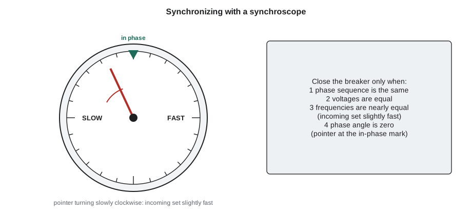
Before an incoming generator's breaker can be closed onto a live bus, four conditions must be met, a process called synchronizing:
- The phase sequence must be the same. This is checked once, at commissioning or after any work on the connections.
- The voltages must be equal, adjusted with the incoming set's voltage regulator.
- The frequencies must be nearly equal, adjusted with the governor so that the incoming machine runs very slightly fast.
- The phase angle must be zero: the voltage waves must be in step at the instant the breaker closes.
A synchroscope shows the phase angle and the frequency difference. Its pointer rotates clockwise, toward FAST, when the incoming machine is faster than the bus, and the operator or an automatic synchronizer closes the breaker as the pointer approaches twelve o'clock and moves slowly. Many installations also have a synch-check relay that blocks the breaker if the conditions are not met. Closing out of phase produces a violent current surge and torque that can damage the generator, the coupling and the prime mover.
Once in parallel, a generator's speed is locked to the bus frequency. Opening the governor no longer makes it faster; it makes it take more kW. Raising the excitation no longer raises the bus voltage much; it makes the machine supply more kvar. If the prime mover loses power while the breaker is still closed, the generator draws power from the bus and runs as a motor, which a reverse power relay detects and trips.
Protective relays
Protective relays watch the currents and voltages of generators, transformers, feeders and motors, and trip the right breaker when they detect a fault or abnormal condition. Each function has a standard device number from the IEEE C37.2 list, used on drawings and relay labels. The common ones in a plant are:
| Device | Function | What it protects against |
|---|---|---|
| 50 / 51 | Instantaneous and time overcurrent | Short circuits and overloads on feeders, transformers and motors |
| 50G / 51G | Ground overcurrent | Faults from a phase to ground |
| 27 / 59 | Undervoltage and overvoltage | Loss of supply, voltage regulator failure |
| 81 | Frequency | Underfrequency or overfrequency from a governor problem or overload |
| 32 | Directional power | Reverse power: a generator motoring |
| 40 | Loss of field | Excitation failure on a generator |
| 46 | Negative sequence current | Unbalanced loads or an open phase |
| 86 | Lockout relay | Holds breakers tripped until manually reset after a protective trip |
| 87 | Differential | Internal faults in a generator, transformer or bus |
An operator does not adjust relays, but should know what each trip means. A generator or transformer that has tripped on its differential relay has almost certainly suffered an internal fault and must not be re-energized until it has been tested. A trip that is held by an 86 lockout relay is held for a reason: the lockout is reset only after the cause is understood, and in most plants only with the chief engineer's or the electrician's agreement.
Switchgear, breakers and buses
Switchgear is the general term for the assemblies of breakers, switches, buses, instrument transformers and relays that distribute power and isolate faults. In a plant like Cantwell it is arranged in a few levels:
- Medium-voltage switchgear at 13.8 kV, belonging partly to the utility, with the service entrance, the revenue meter and the main transformer's primary breaker or fused switch.
- The main switchboard at 600 V, fed from the transformer secondary, with the main breaker, the transfer switch and feeder breakers to each motor control centre.
- Motor control centres (MCCs): lineups of plug-in units or buckets, each holding a breaker or fused disconnect, a starter or drive and its controls, for one motor.
- Panelboards for lighting, receptacles and small loads, fed through dry-type transformers.
Circuit breakers interrupt current, including fault current, and can be reset and closed again. Molded-case breakers are used in panelboards and MCCs. Power circuit breakers, larger and adjustable, are used for mains and large feeders, often in drawout form so they can be racked out to a disconnected position for maintenance. At medium voltage, vacuum breakers interrupt the arc inside a sealed vacuum bottle. Fuses interrupt fault current very quickly and limit the energy let through, but must be replaced after operating. Disconnect switches isolate equipment but are not designed to interrupt load current or faults; opening a disconnect under load can draw a dangerous arc.
Every breaker and fuse must have an interrupting rating greater than the largest fault current that can flow at its location. A breaker asked to interrupt more than its rating can fail violently.
Worked problem
Available fault current at the main switchboard
Cantwell's main transformer is rated 2,500 kVA, 13.8 kV to 600 V, with an impedance of 5.75 in 100. Estimate its full-load secondary current and the largest fault current it could deliver to a bolted fault at the main switchboard, assuming the utility supply is infinitely strong.
Show solution
- Full-load secondary current:
- \[I_{FL} = \frac{2{,}500{,}000}{\sqrt{3} \times 600} = 2{,}406 \text{ A}\]
- The impedance in per unit limits the fault current:
- \[I_{SC} = \frac{I_{FL}}{Z} = \frac{2{,}406}{0.0575} \approx 41{,}800 \text{ A}\]
Answer: About 2,400 A at full load and about 42 kA into a fault, before motor contribution and cable impedance are counted. The main breaker and the feeder breakers must be rated to interrupt at least that, and the same figure feeds the arc flash study in lesson 4.
The single-line diagram
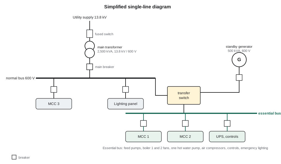
A single-line diagram, or one-line diagram, shows a three-phase power system with one line standing for all three conductors. It is the operator's map of the electrical system: where power comes from, where it can be isolated, and what each breaker feeds. Standard symbols show transformers as two linked circles, breakers as small squares, fuses, disconnects, generators as circles with a G, motors with an M, and the ratings of each. Every plant should have an up-to-date single-line diagram posted in the main electrical room, and the operator should be able to trace any motor back to its source.
Transfer switches and loss of supply
The automatic transfer switch (ATS) monitors the normal supply. When the voltage or frequency falls outside its limits for a set time, it signals the generator to start; once the generator is at rated voltage and frequency, it transfers the essential loads. When the normal supply returns, the ATS waits for a retransfer delay, often 15 to 30 minutes, to make sure the supply is stable, then transfers back and lets the generator run unloaded for a cooldown period before stopping. At Cantwell the retransfer delay is 30 minutes, so the plant returned to utility power at 15:39 and the generator stopped at 15:44.
Because the generator carries emergency lighting and fire alarm loads as well as process loads, it is installed and tested as an emergency power supply to CSA C282, with the monthly and yearly tests described in PWR-230 lesson 3.
Not every load in a plant can go on the generator. The essential bus at Cantwell carries the two motor feed pumps, the forced draft fans of boilers 1 and 2, one hot water circulating pump, the instrument air compressors, the control system and the emergency lighting. The chiller, the cooling tower, the third boiler's fan and the second hot water pump are left on the normal bus and must wait for the utility. When an operator wants to add a load during an outage, the question is always whether the generator has the kW and the current to spare, and whether the motor's starting current will pull the voltage down too far.
After the September 20 outage, Pilar's log entry ran to a full page. She listed the time of each event from the control system's sequence-of-events record, the generator's peak load, the motors restarted and in what order, the turbine run time, and two items for follow-up: the boiler 2 fan had not been restarted because the generator would have reached about 90 in 100 of its kW rating, and the uninterruptible power supply for the control system had alarmed on low battery after only 40 minutes, far short of its design time. Ruaridh replaced the UPS batteries that week.
Batteries and uninterruptible power supplies
Control systems, protective relays and breaker trip coils cannot be allowed to lose power when the main supply fails, so plants keep stored energy supplies:
- A station battery, usually 125 V or 48 V DC, with its charger, supplies breaker trip and close circuits and relays. A breaker that cannot trip because its battery is flat cannot clear a fault.
- An uninterruptible power supply (UPS) supplies the control system, the operator workstations and critical instruments. Its batteries carry the load from the moment the supply fails until the generator picks up and, if the generator fails, for long enough to shut the plant down safely.
Operators check battery chargers and UPS alarms on their rounds, keep battery rooms ventilated because charging batteries can release hydrogen, and note any alarm in the log. Batteries age quietly; regular load tests are the only way to know a battery will last its design time.
Common mistakes
MistakeThinking that opening a paralleled generator's governor raises the frequency.
InsteadIn parallel the speed is locked to the bus; more fuel makes the machine take more kW.
MistakeClosing a breaker onto a live bus without checking synchronism.
InsteadVoltage, frequency and phase angle must match; an out-of-phase closure can wreck the machine.
MistakeResetting an 86 lockout relay to restore power quickly.
InsteadA lockout holds a protective trip; find the cause first and reset only with the proper authority.
MistakeOpening a disconnect switch to stop a running load.
InsteadDisconnects are not made to interrupt load current; stop the load with its breaker or starter first.
MistakeStarting several motors at once on the standby generator.
InsteadStart one large motor at a time and let the voltage and frequency recover between starts.
Summary and key terms
- A synchronous generator's frequency is PN ÷ 120; the governor sets speed and kW, the voltage regulator sets voltage and kvar.
- Generators are rated in kVA at 0.8 power factor and in kW; watch both current and kW on load.
- Paralleling needs the same phase sequence, equal voltages, nearly equal frequencies and zero phase angle.
- Protective relays carry standard device numbers; a differential or lockout trip is investigated before re-energizing.
- Switchgear, breakers and fuses must be rated to interrupt the available fault current, roughly full-load current divided by transformer impedance.
- The single-line diagram is the operator's map; the transfer switch moves essential loads to the generator.
- Exciter
- The source of DC current for a generator's field winding.
- Automatic voltage regulator
- A controller that adjusts a generator's excitation to hold its output voltage.
- Synchronizing
- Matching an incoming generator's voltage, frequency and phase angle to a live bus before closing its breaker.
- Synchroscope
- An instrument that shows the phase angle and frequency difference between an incoming generator and a bus.
- Interrupting rating
- The largest fault current a breaker or fuse can safely interrupt.
- Single-line diagram
- A drawing that shows a three-phase power system with one line for all three conductors.
- Automatic transfer switch
- A switch that transfers loads from the normal supply to a standby generator and back.
Practice problems
Work each problem on paper first, then reveal the answer to check.
At what speed must a six-pole generator turn to produce 60 Hz?
Show answer
N = 120 × 60 ÷ 6 = 1,200 r/min.
A 750 kVA, 600 V generator carries 520 kW at 0.80 power factor. What is its current, and is it within rating?
Show answer
S = 650 kVA; I = 650,000 ÷ (1.732 × 600) ≈ 625 A; rated current is 722 A, so it is within rating.
A 1,500 kVA, 600 V transformer has an impedance of 5.5 in 100. Estimate the available fault current at its secondary.
Show answer
IFL = 1,443 A; ISC ≈ 1,443 ÷ 0.055 ≈ 26,200 A.
Lesson quiz · 5 questions
Score 60% or more to complete this lesson.
Create a free account to save your progress, take quizzes and earn a certificate.