
PLB-230 · Lesson 5 of 12 · 21 min
Sizing gas piping: loads, pressure drop and the longest-length method
Back in the café, Dana pulled out the tenant's drawings. The café's previous designer had run a 1-inch main from the café meter to the kitchen, and the range, fryer and combination oven all hung off it. The dynamic pressure test from lesson 3 had shown a drop of more than twice what the sizing tables allow. "Let's size it properly," Dana said, "and see whether that 1-inch main was ever right."
Gas piping must deliver enough gas to every appliance, at a pressure inside the appliance's inlet range, while all the connected appliances fire at once. Undersized piping starves appliances, which underfire, light roughly and may produce carbon monoxide. Oversized piping wastes money but does no harm. This lesson explains the information needed to size a system, how the code's sizing tables are built, and the longest-length method most commonly used for low-pressure systems.
What sizing needs to know
Before sizing anything, the fitter gathers five pieces of information. The first is the gas: natural gas or propane, because the tables differ. The second is the delivery pressure at the start of the system: standard low pressure or an elevated pressure such as 2 psi. The third is the allowable pressure drop through the piping, which the designer chooses so that the pressure at the farthest appliance stays above its minimum inlet pressure. The fourth is the load: the input of every appliance, converted to flow. The fifth is the length of piping from the start of the system to each outlet.
For a standard low-pressure natural gas system starting at about 1.75 kPa (7 in. w.c.), the common design pressure drop is 0.125 kPa (0.5 in. w.c.), which leaves a comfortable margin above the minimum inlet pressure of most appliances. Larger drops can be used where the code allows and the appliances can tolerate them, which permits smaller pipe, but the fitter must then confirm that every appliance still receives enough pressure. The code provides tables for several pressure drops and for elevated pressures.
The load is the total input of all appliances that the section of pipe supplies, without any diversity allowance in most cases. The codes assume everything may run at once, which is realistic for many buildings on a cold morning. Gas flow equals input divided by the heating value; for natural gas, sizing usually uses a round 1,000 Btu per cubic foot. Where an appliance's input is not known, the code lists typical inputs for common appliances, but the rating plate is always better.
The length is measured along the pipe, including vertical runs, from the point of delivery, usually the meter outlet or a regulator outlet, to the outlet in question. The code's tables allow for an ordinary number of fittings in a typical layout. Where a system has an unusual number of fittings, the designer adds their equivalent length, from a table of equivalent lengths, to the measured length.
How the sizing tables are built
The capacity of a gas pipe depends on its inside diameter, its length, the pressure drop allowed, and the density of the gas. The code's low-pressure tables are calculated from a standard flow formula. In the form used in US fuel gas codes, capacity in cubic feet per hour equals a constant times the inside diameter raised to about the 2.6 power, times the pressure drop divided by the gas's relative density factor and the length, all raised to about the 0.54 power. B149.1 publishes its own tables in its sizing annex. The fitter normally reads capacities from the tables rather than calculating, but the formula explains three things every fitter should know.
In this formula, Q is the flow in cubic feet per hour, D the inside diameter in inches, ΔH the pressure drop in inches of water column, L the length in feet and C_r a factor for the gas, about 0.61 for natural gas. The first lesson is that diameter dominates: because capacity rises with diameter to the power 2.6, one size up roughly doubles capacity. The second is that length matters much less: doubling the length cuts capacity by only about 30 percent. The third is that a larger allowed pressure drop raises capacity, but not in proportion. The formula is shown here in US units because that is how it is published; the practice tables below convert it to metric.
| Length (m) | 1/2 | 3/4 | 1 | 1-1/4 | 1-1/2 | 2 |
|---|---|---|---|---|---|---|
| 5 | 38.6 | 80.7 | 152 | 312 | 468 | 901 |
| 10 | 26.5 | 55.5 | 105 | 215 | 321 | 619 |
| 15 | 21.3 | 44.5 | 83.9 | 172 | 258 | 497 |
| 20 | 18.2 | 38.1 | 71.8 | 147 | 221 | 425 |
| 25 | 16.2 | 33.8 | 63.6 | 131 | 196 | 377 |
| 30 | 14.6 | 30.6 | 57.7 | 118 | 177 | 342 |
The longest-length method
The longest-length method is the simplest and most common way to size a low-pressure system with the code tables. It treats the whole system as if every outlet were as far from the meter as the farthest one. That is conservative, because outlets closer to the meter would have more pressure available, but it is quick and reliable. The steps are always the same.
- Draw the piping layout as a simple line diagram, from the point of delivery to every outlet, and label each section.
- Measure the length from the point of delivery to the most remote outlet. That is the longest length.
- In the table for the gas, pressure and allowed drop, choose the length row equal to or next longer than the longest length. Use only that row for the whole system.
- For each section, add up the loads of every appliance downstream of it.
- Move along the chosen row to the first size whose capacity equals or exceeds the section's load. That is the pipe size for the section.
Two refinements exist. The branch length method, where the adopted code permits it, sizes each branch using the length from the point of delivery to the outlet at the end of that branch, and sizes the main using the longest length; it can give smaller branches near the meter. For elevated pressure systems, the designer sizes the piping from the meter to each line regulator using the elevated-pressure tables, with the regulator's inlet pressure requirement as the limit, and then sizes the low-pressure piping downstream of each regulator separately, starting from the regulator outlet.
Worked problem
Sizing the café piping
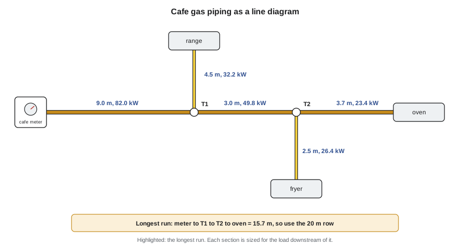
The café meter delivers standard low-pressure natural gas. The range is 32.2 kW, the fryer 26.4 kW and the combination oven 23.4 kW. Lengths: meter to T1, 9.0 m; T1 to the range, 4.5 m; T1 to T2, 3.0 m; T2 to the fryer, 2.5 m; T2 to the oven, 3.7 m. Size each section with the practice table.
Show solution
- Longest run: meter → T1 → T2 → oven = 9.0 + 3.0 + 3.7 = 15.7 m. Use the 20 m row.
- Meter to T1 carries everything: 32.2 + 26.4 + 23.4 = 82.0 kW. The 1-inch capacity is 71.8 kW, too small; 1-1/4 inch carries 147 kW. Use 1-1/4 inch.
- T1 to range: 32.2 kW. 1/2 inch carries 18.2, 3/4 inch carries 38.1. Use 3/4 inch.
- T1 to T2: 26.4 + 23.4 = 49.8 kW. 3/4 inch carries 38.1, too small; 1 inch carries 71.8. Use 1 inch.
- T2 to fryer: 26.4 kW, and T2 to oven: 23.4 kW. Both use 3/4 inch.
Answer: The main should be 1-1/4 inch. The existing 1-inch main is undersized, which explains the large pressure drop measured under full load.
# Longest-length sizing of the Kingsway cafe piping (natural gas, low pressure)
# Capacities come from a standard low-pressure flow formula (relative density 0.6,
# 0.125 kPa drop, Schedule 40 steel), rounded. On the job, use the B149.1 tables.
ids = {"1/2": 0.622, "3/4": 0.824, "1": 1.049, "1-1/4": 1.380, "1-1/2": 1.610, "2": 2.067}
def cap_kw(d_in, length_m, drop_inwc=0.5, cr=0.6094):
    cfh = 2313 * d_in ** 2.623 * (drop_inwc / (cr * length_m * 3.2808)) ** 0.541
    return cfh * 1000 / 3412            # about 1,000 Btu per cubic foot
columns_m = [5, 10, 15, 20, 25, 30]
sections = {  # name: (load kW, path to the farthest outlet passes through it?)
    "meter to T1": 32.2 + 26.4 + 23.4,
    "T1 to range": 32.2,
    "T1 to T2": 26.4 + 23.4,
    "T2 to fryer": 26.4,
    "T2 to oven": 23.4,
}
longest = 9.0 + 3.0 + 3.7                     # meter -> T1 -> T2 -> oven
col = next(c for c in columns_m if c >= longest)
print(f"longest run {longest} m, use the {col} m column")
for name, kw in sections.items():
    size = next(s for s, d in ids.items() if cap_kw(d, col) >= kw)
print(f"{name:12s} {kw:5.1f} kW -> {size} in (capacity {cap_kw(ids[size], col):5.1f} kW)")longest run 15.7 m, use the 20 m column meter to T1 82.0 kW -> 1-1/4 in (capacity 147.4 kW) T1 to range 32.2 kW -> 3/4 in (capacity 38.1 kW) T1 to T2 49.8 kW -> 1 in (capacity 71.8 kW) T2 to fryer 26.4 kW -> 3/4 in (capacity 38.1 kW) T2 to oven 23.4 kW -> 3/4 in (capacity 38.1 kW)
The script reaches the same answer as the hand method and makes it easy to test changes. If the café owner adds a 15 kW (about 50,000 Btu/h) griddle at the end of the line, rerunning the script shows at once which sections must grow. Dana's recommendation to the tenant was to replace the 1-inch main with 1-1/4 inch before the griddle was added.
Elevated pressure and propane
Elevated pressure changes the picture dramatically. At 14 kPa (2 psi) with a typical allowed drop of 7 kPa (1 psi), a 1/2-inch pipe can carry many times what it carries at low pressure. That is why Kingsway's house main, which feeds 1,148,000 Btu/h of equipment on the roof and in the mechanical room, is only 1-1/2 inch steel for most of its height, with line regulators at each group of appliances. The elevated-pressure tables in the code are used in the same way as the low-pressure tables, and the regulator's minimum inlet pressure, from its manufacturer's data, sets the limit at the end of the run.
Propane has a higher heating value and density than natural gas, so the same pipe carries less volume but more energy. The code has separate tables for propane, in Btu per hour or kilowatts, for the low-pressure piping after the second-stage regulator and for the higher-pressure piping between the first and second stages. Natural gas tables must never be used for propane, or the reverse.
For CSST and other flexible systems, the manufacturer's sizing tables apply, because corrugations create more friction than smooth steel. CSST is sized by length and load like steel, but the capacity for a given nominal size is lower, and each bend and fitting counts. Copper tubing and polyethylene have their own tables too.
Checking an existing system
When an appliance is added to an existing building, the fitter checks the existing piping and meter as if sizing from scratch, including the new load. The most common mistake in gas work is adding a large appliance, such as a tankless water heater, a pool heater or a commercial range, to piping sized decades ago for a furnace and a water heater. The new appliance may light and run alone but starve when the furnace runs too, producing poor combustion exactly when it is hardest to notice.
The meter has a capacity too. The utility sizes the meter and service for the expected load, and a significant added load must be reported to the utility so that it can confirm or change the meter. A pressure drop measured at the meter outlet under load, compared with the static pressure, shows whether the meter and service keep up.
Common mistakes
MistakeUsing the length to each appliance instead of the longest length.
InsteadUnder the longest-length method, use one row for the whole system.
MistakeSizing from the appliance's output instead of its input.
InsteadSize on input, the fuel the appliance burns.
MistakeUsing natural gas tables for propane.
InsteadUse the tables for the gas being piped.
MistakeSizing CSST with steel pipe tables.
InsteadUse the CSST manufacturer's sizing tables.
MistakeAdding a large appliance without rechecking the piping and meter.
InsteadResize the affected sections and tell the utility about the added load.
Summary and key terms
- Sizing needs the gas, delivery pressure, allowed drop, loads and lengths.
- Low-pressure natural gas systems commonly allow a 0.125 kPa (0.5 in. w.c.) drop.
- Capacity rises with roughly the 2.6 power of diameter; length has a much smaller effect.
- The longest-length method uses one table row, chosen for the farthest outlet, for every section.
- Each section carries the total load of every appliance downstream.
- Elevated pressure greatly increases capacity; low-pressure piping is sized from each regulator outlet.
- Propane, CSST, copper and PE each have their own tables.
- Connected load
- The total input of every appliance supplied by a system or section.
- Allowable pressure drop
- The pressure loss permitted between the point of delivery and the farthest outlet.
- Longest length
- The piping length from the point of delivery to the most remote outlet.
- Equivalent length
- The length of straight pipe that causes the same pressure drop as a fitting.
- Point of delivery
- Where the customer piping starts, usually the meter or regulator outlet.
- Branch length method
- A sizing method that uses the length to the end of each branch for that branch.
Practice problems
Work each problem on paper first, then reveal the answer to check.
Which row of the table does the longest-length method use?
Show answer
The row equal to or next longer than the longest length, for every section.
A section feeds appliances of 20 kW and 15 kW. What load does it carry?
Show answer
35 kW.
Using the 10 m row, which size carries 50 kW?
Show answer
3/4 inch, which carries 55.5 kW.
Why are smaller pipes possible on elevated-pressure systems?
Show answer
Capacity rises greatly with pressure and allowed drop.
What tables are used for CSST?
Show answer
The manufacturer's sizing tables.
What must be done before adding a large appliance to existing piping?
Show answer
Recheck the piping and meter with the new load included.
Lesson quiz · 5 questions
Score 60% or more to complete this lesson.
Create a free account to save your progress, take quizzes and earn a certificate.