
PET-310 · Lesson 3 of 12 · 19 min
Drill string and bits
The rig turns and lifts the drill string, but the string itself has to carry those loads for kilometres underground while being bent through the curve, rubbed along the lateral and vibrated by the bit. Marcus gives Ethan the offset well's bit record and bottomhole assembly sheets. 'The string has two jobs that pull in opposite directions,' he says. 'It has to push weight onto the bit, and it has to stay in tension where the pipe is weakest. Designing it is about deciding which part does which job.'
Components of the drill string
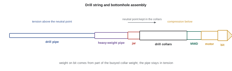
Drill pipe makes up most of the string. Each joint is a seamless steel tube about 9.5 m (31 ft) long with thick tool joints welded to its ends; the tool joints carry the threaded connections. Drill pipe is specified by outside diameter, weight per unit length, steel grade and connection type. Common grades are E, X, G and S, with minimum yield strengths from about 517 to 931 MPa (75,000 to 135,000 psi). Pipe in service is inspected and classed by remaining wall thickness, so a used string has lower ratings than new pipe.
The bottomhole assembly (BHA) is the lower part of the string, between the drill pipe and the bit. It usually contains drill collars, heavy thick-walled tubes that provide weight and stiffness; heavy-weight drill pipe as a transition between the stiff collars and the flexible pipe; stabilizers that centre the assembly and control its direction; a drilling jar that can deliver an impact to free stuck pipe; measurement-while-drilling (MWD) and logging-while-drilling (LWD) tools; and, in directional wells, a mud motor or rotary steerable tool. In horizontal wells, much of the 'weight' comes from pipe and heavy-weight pipe in the vertical section, because collars lying in the lateral add drag but no weight on bit.
Tension, compression and the neutral point
Hanging in the hole, the string is in tension from its own weight, greatest at the top. When the driller slacks off to put weight on the bit, the lower part of the string goes into compression. The point where axial stress changes from tension to compression is called the neutral point. Drill pipe is slender and its connections fatigue quickly if it is bent back and forth in compression, so in vertical hole the rule is to keep the neutral point inside the drill collars: use only part, often 80 to 85 percent, of the buoyed weight of the collars as weight on bit.
In deviated and horizontal wells the picture changes. Pipe lying on the low side of an inclined hole is supported along its length and can carry compression without buckling much, up to a critical load that depends on its stiffness, the hole clearance and the inclination. That is why horizontal wells can be drilled with drill pipe in compression in the curve and lateral, with heavy pipe placed higher up in the vertical section. Torque and drag models (lesson 11) check that the pipe does not buckle severely.
Designing for tension
The top joint of drill pipe carries the whole buoyed weight of the string below it. The design load for tension is usually set at about 90 percent of the pipe's rated tensile capacity, and the string is designed so that, when hanging free, it still leaves a margin of overpull: extra pull the driller can apply to free stuck pipe without exceeding the design load. The maximum length of drill pipe for a given BHA follows from these numbers.
Other design checks include collapse, for example when the string is run with an empty section or used for a drill stem test; burst; torsion, since connections must not be over-torqued; and fatigue, especially in high dogleg sections where the rotating pipe bends back and forth with every revolution.
# Drill string design: weight on bit from collars, neutral point and maximum length of drill pipe
SI = True
mw = 1150 / 119.826 if SI else 10.2           # mud weight, ppg
bf = 1 - mw / 65.5
wc, Lc = 83.0, 540.0                          # drill collars: lb/ft and length ft (6-1/2 in collars)
wdp, ydp = 16.6, 395000.0                     # 4 in (101.6 mm) pipe, adjusted weight lb/ft and tensile rating lb (illustrative)
wob_max = 0.85 * wc * Lc * bf                 # keep the neutral point in the collars: use 85 percent of buoyed collar weight
print(f"buoyancy factor {bf:.3f}")
print(("maximum weight on bit " + (f"{wob_max*0.004448:,.0f} kN" if SI else f"{wob_max:,.0f} lb")))
for wob in (25000, 35000):
    npt = wob / (wc * bf)                     # neutral point above the bit, inside the collars if less than Lc
    print(f"WOB {wob*0.004448:,.0f} kN" if SI else f"WOB {wob:,} lb", "-> neutral point", f"{npt*0.3048:,.0f} m" if SI else f"{npt:,.0f} ft", "above the bit")
pa = 0.9 * ydp                               # design load at 90 percent of rated yield
mop = 100000.0                               # margin of overpull for stuck pipe
Ldp = (pa - mop) / (wdp * bf) - wc * Lc / wdp
print("maximum length of drill pipe", f"{Ldp*0.3048:,.0f} m" if SI else f"{Ldp:,.0f} ft", "with a margin of overpull of", f"{mop*0.004448:,.0f} kN" if SI else f"{mop:,.0f} lb")buoyancy factor 0.853 maximum weight on bit 145 kN WOB 111 kN -> neutral point 108 m above the bit WOB 156 kN -> neutral point 151 m above the bit maximum length of drill pipe 4,674 m with a margin of overpull of 445 kN
With 540 ft (about 165 m) of 6-1/2 in collars in 1,150 kg/m³ mud, the collars can give up to about 145 kN of weight on bit while keeping the neutral point in them; at 111 kN the neutral point is about 108 m above the bit. The tensile check allows about 4,670 m of drill pipe with 445 kN of overpull, far more than the 3,260 m planned, so tension is not the limiting factor in this shallow well. In the lateral the collars would add drag but no weight, so the BHA in the lateral will be short and the weight will come from pipe in the vertical section.
Drill bits
Two main bit types are used. Roller cone bits have two or three cones that rotate as the bit turns, with steel teeth or tungsten carbide inserts that crush and gouge the rock. Fixed-cutter bits have no moving parts: polycrystalline diamond compact (PDC) cutters set in a steel or matrix body shear the rock like a plane cutting wood. PDC bits now drill most footage in sedimentary basins, because they drill faster and last longer in shales and sandstones; roller cone bits are still used in very hard, abrasive or interbedded rock and in some large-diameter surface holes. Hybrid bits combine both cutting actions.
The International Association of Drilling Contractors (IADC) publishes classification codes for both bit types, so bits from different makers can be compared, and a grading system for dull bits. When a bit is pulled, the crew grades it for cutter wear, location of wear, bearing condition, gauge and the reason it was pulled. Reading dull grades along the offset wells tells the engineer whether the bits wore out, were damaged by vibration, balled up in sticky shale or were pulled for other reasons, and points to better bit selection.
Weight, speed and rate of penetration
Rate of penetration (ROP) depends on weight on bit, rotary speed, bit type and condition, hydraulics, mud properties and, above all, the rock. For PDC bits, ROP rises roughly in proportion to weight on bit and rotary speed until a limit: the 'founder point', where more weight no longer helps because the bit is not being cleaned fast enough or the cutters are fully buried, or a point where vibration sets in. Modern rigs run drill-off tests and use real-time data to find the best combination, and many record mechanical specific energy, the energy spent per unit volume of rock removed, to spot inefficient drilling.
When mechanical specific energy rises far above the strength of the rock, energy is being lost to vibration, bit balling or poor cleaning rather than cutting. Three kinds of vibration damage bits and BHAs: axial (bit bounce), lateral (whirl) and torsional (stick-slip, where the bit stops and then spins rapidly). Each has its own remedy, such as changing weight and speed, using different stabilizer placement or using a shock tool.
Worked problem
Neutral point and maximum weight on bit
A BHA has 150 m of collars weighing 120 kg/m in 1,200 kg/m³ mud. Find the maximum weight on bit that keeps the neutral point in the collars, using 85 percent.
Show solution
- BF = 1 − 1,200/7,850 = 0.847.
- Buoyed collar weight = 150 × 120 × 9.81 × 0.847 = 149,600 N = 149.6 kN.
- WOB max = 0.85 × 149.6 = 127 kN.
Answer: About 127 kN.
Inspection and care of the string
Drill pipe and BHA components are expensive and their failure underground is costly. Connections are made up to a specified torque with clean thread compound; under-torqued connections can leak and wash out, and over-torqued ones can be damaged. Pipe is inspected regularly for wall loss, cracks and worn tool joints, following industry inspection standards, and BHA components are inspected for fatigue cracks after set rotating hours. A washout, a small hole cut by mud through a cracked connection, shows on the rig as a gradual loss of pump pressure; if it is not caught, the pipe can part. Drillers are trained to stop and look for a washout when pressure falls without explanation.
Bottomhole assemblies for different jobs
The arrangement of stabilizers in the BHA controls how the bit tends to move. A packed or pendulum assembly with a stabilizer near the bit and others above it resists changes in angle and holds a straight course; a pendulum assembly with no near-bit stabilizer lets gravity pull the bit back toward vertical, used to drop angle or to drill vertical holes in formations that push the bit sideways; and a fulcrum assembly with a near-bit stabilizer and a flexible section above it builds angle when weight is applied. In modern horizontal wells, steering is done with motors and rotary steerable tools (lesson 10), but the same principles explain why BHA design affects hole quality, vibration and the ability to follow the plan.
In the 03-22 well's lateral, the BHA will be short: the bit, a rotary steerable tool, an MWD tool with gamma ray, a few non-magnetic collars to keep the magnetic survey sensors away from steel, and then drill pipe. Heavy-weight pipe and a jar will be placed in the vertical section above the kickoff point, where their weight pushes the string and the jar can work freely. This arrangement, sometimes called an inverted string, is standard for long horizontal wells.
Learning from bit records
The offset bit records Marcus gave Ethan list, for each bit run, the bit type and size, the depths in and out, the hours, the average weight on bit, rotary speed and flow rate, the rate of penetration, the dull grade and the reason pulled. Plotting cost per metre or per foot for each bit run against depth shows which designs perform best in each formation. In the offset wells, PDC bits with five blades and 16 mm cutters gave the best results in the lateral, while bits pulled for 'penetration rate' showed broken cutters on the shoulder, a sign of vibration. Ethan recommends the same design with a shock-absorbing sub and a drilling parameter roadmap that keeps the rotary speed out of the range where stick-slip was recorded.
Common mistakes
MistakePutting the full buoyed weight of the collars on the bit.
InsteadUse about 80 to 85 percent so the neutral point stays in the collars.
MistakeIgnoring buoyancy in string weight calculations.
InsteadMultiply air weights by the buoyancy factor for the mud in use.
MistakeUsing new-pipe ratings for a used string.
InsteadUse ratings for the inspected class of the pipe.
MistakeAdding more weight on bit when ROP stops increasing.
InsteadCheck for founder, poor cleaning or vibration before adding weight.
Summary and key terms
- The drill string consists of drill pipe and a BHA of collars, heavy-weight pipe, stabilizers, jars, MWD tools, motors and the bit.
- Keep the neutral point in the collars in vertical hole; in deviated hole pipe can carry some compression on the low side.
- Tension design uses about 90 percent of rated capacity less a margin of overpull.
- PDC bits drill most footage today; roller cone bits suit hard, abrasive or interbedded rock.
- ROP depends on weight, speed, hydraulics and rock; mechanical specific energy and vibration data reveal inefficient drilling.
- Bottomhole assembly (BHA)
- The lower part of the drill string, from the bit to the drill pipe.
- Drill collar
- A heavy, thick-walled tube used to provide weight and stiffness above the bit.
- Neutral point
- The point in the string where axial stress changes from tension to compression.
- Margin of overpull
- Extra pull available above the hanging string weight before reaching the design load.
- PDC bit
- A fixed-cutter bit with polycrystalline diamond compact cutters.
- Mechanical specific energy
- Energy spent per unit volume of rock removed.
- Stick-slip
- Torsional vibration in which the bit stops and then spins rapidly.
Practice problems
Work each problem on paper first, then reveal the answer to check.
Why do horizontal wells place heavy pipe in the vertical section rather than collars in the lateral?
Show answer
In the lateral the weight of collars rests on the low side and adds drag, not weight on bit; weight placed in the vertical section pushes the bit.
What does a rising MSE with constant ROP suggest?
Show answer
Energy is being wasted, for example in vibration, bit balling or poor hole cleaning.
Name the information in an IADC dull grade.
Show answer
Cutter or tooth wear, wear location, bearing condition, gauge, other characteristics and the reason pulled.
What does a slow loss of pump pressure while drilling suggest?
Show answer
A possible washout in the string; stop and check before the pipe parts.
Lesson quiz · 5 questions
Score 60% or more to complete this lesson.
Create a free account to save your progress, take quizzes and earn a certificate.