
PET-310 · Lesson 1 of 12 · 21 min
The drilling process and well planning
Ethan Cardinal has moved from reservoir work into the drilling and completions group at Prairie Crest Energy Ltd. in Calgary. His new mentor is Marcus Obi, the senior drilling engineer, and his first assignment is the Tamarack 03-22 horizontal well: a horizontal well that will land in the Cardium at about 1,560 m true vertical depth and run a 1,600 m lateral under the Tamarack Lake field. 'Everything you learned about rock and fluids now turns into hardware and hours,' Marcus says. 'A drilling program is a promise: this hole, this mud, this casing, this many days, this much money, and nobody gets hurt. Our job this term is to write that promise and then check every number in it.'
This course follows that well from the first sketch to the final drilling program. Each lesson takes one part of the problem: the rig, the drill string, the mud, the hydraulics, the formation pressures, well control, casing, cement, directional drilling and the problems that cost time. The last lesson puts them together. This first lesson describes how a well is drilled, the vocabulary drilling engineers use, and how a well plan and its cost estimate are built.
What drilling has to achieve
A well is a pressure vessel built in stages inside the earth. It must reach the target, at the right place and angle, without losing control of formation fluids, without damaging the formations it is meant to produce, and without contaminating the groundwater it passes through. It must be built at a cost the project can carry, because drilling and completing the wells is usually the largest single capital cost in an oil or gas development. In a horizontal shale or tight-oil play, wells are drilled in repeated patterns, so a saving of one day per well, repeated on hundreds of wells, is worth a great deal.
Drilling engineers therefore balance three goals that sometimes conflict: safety and well integrity, cost and time, and the quality of the final wellbore for the completion and production teams. A cheaper casing design that leaves no margin against a kick is not acceptable. Neither is a perfectly safe plan that takes so long the well is uneconomic. The drilling program is where those trade-offs are written down and approved.
How a well is drilled, in sequence
Rotary drilling turns a bit at the end of a string of steel pipe while pumping drilling fluid down the pipe, out through the bit and back up the annulus between the pipe and the hole. The fluid cools and cleans the bit, carries the rock cuttings to surface, and, most important, exerts hydrostatic pressure that holds formation fluids in place. At surface the cuttings are screened out and the fluid is pumped down again in a closed loop.
The hole is drilled in sections. The first section, the surface hole, is drilled through the shallow sediments and freshwater aquifers. Steel casing is run to the bottom of that section and cemented back to surface, isolating the groundwater and giving a strong anchor for the blowout preventer stack. The next section is drilled with a smaller bit through the casing, and the process repeats: drill, log or survey as needed, run casing, cement, test, and drill out. Each casing string is a step down in diameter, which is why well design starts from the bottom: the size of hole needed at the target sets the sizes of everything above it.
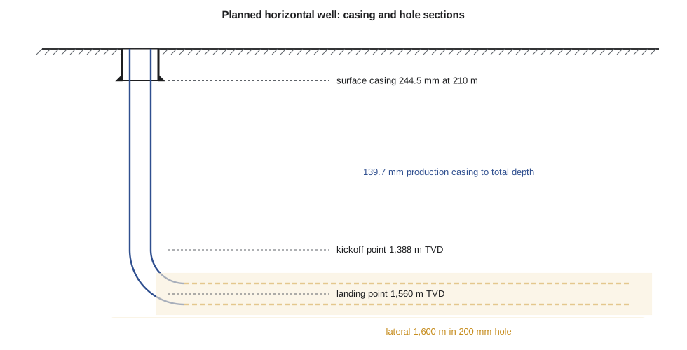
For the 03-22 well the design is simple, typical of Cardium horizontals: a 311 mm surface hole with 244.5 mm surface casing set at about 210 m, then a single 200 mm hole drilled vertically to the kickoff point, built to horizontal and drilled along the lateral. A 139.7 mm production casing is run from surface to total depth and cemented, a 'monobore' design that leaves a single, large casing for the completion.
Well types and trajectories
A vertical well goes straight down. A directional well is steered away from vertical to reach a target that is offset from the surface location, for example under a lake, a town or from a shared pad. A horizontal well is a directional well that turns until it runs roughly parallel to the reservoir and stays in it for a long distance. In tight reservoirs, a long horizontal well with many hydraulic fracture stages contacts far more rock than a vertical well and is the main reason tight-oil and shale development became economic.
A horizontal trajectory has three parts. The vertical section runs from surface to the kickoff point. The build section, or curve, turns the well from vertical to horizontal at a planned build rate, usually stated in degrees per 30 m or per 100 ft. The lateral then holds close to 90 degrees of inclination along the target zone. If the build rate is constant, the curve is an arc of a circle whose radius follows directly from the build rate, and the kickoff point lies one radius above the landing depth.
Here B is the build rate in degrees per unit of measured depth, so R comes out in the same length unit. Two depths matter throughout drilling engineering. Measured depth (MD) is the length along the hole, which sets how much pipe, casing and cement is needed and how long it takes to drill. True vertical depth (TVD) is the vertical distance below the reference point, which sets hydrostatic and formation pressures. In a horizontal well the two differ greatly: the 03-22 well's total measured depth is roughly twice its true vertical depth.
The well planning process
Planning starts with the geology and reservoir teams, who define the target: the zone, its depth, the landing point, the azimuth and length of the lateral, and any hazards known from offset wells. The drilling engineer then gathers offset data: drilling reports, bit records, mud records, casing and cement records, logs and any problems such as lost circulation, stuck pipe or kicks from nearby wells. Offset wells are the single best guide to what the new well will meet.
From that data the engineer builds the pressure profile: pore pressure, fracture gradient and overburden against depth (lesson 6). That profile sets the mud weights and the casing points. Then come the casing design (lesson 8), the cement design (lesson 9), the directional plan (lesson 10), the bit and bottomhole assembly program (lesson 3), the mud program (lesson 4), the hydraulics (lesson 5), and the well control plan (lesson 7). Finally, the time and cost estimate turns all of this into days and dollars.
Plans are reviewed before approval. Many operators hold a 'drill the well on paper' session where the rig contractor, service companies and the operator's team walk through each section, step by step, asking what could go wrong and what the response will be. The plan is then submitted to the regulator as part of the well licence or permit, and the rig crew is briefed before spud.
Regulation of drilling
In Alberta, wells are licensed and regulated by the Alberta Energy Regulator (AER). Its directives set many of the requirements a drilling engineer must design to. Directive 036, Drilling Blowout Prevention Requirements and Procedures, sets the blowout preventer equipment, testing and crew drill requirements by well class. Directive 008, Surface Casing Depth Requirements, sets the minimum depth of surface casing to protect groundwater. Directive 050 covers drilling waste management. The rig crew's competence is supported by industry training such as Energy Safety Canada courses and well control certification.
Regulations set minimums. A good drilling program meets them and then adds the margins the specific well needs, based on offset experience and the consequences of failure. It is the operator, not the regulator or the rig contractor, who is responsible for the well design.
The authority for expenditure
Before money is spent, the well needs an approved authority for expenditure (AFE): a cost estimate that management, and any partners in the well, sign. A drilling AFE has two kinds of cost. Time-dependent costs accrue every day the rig is on location: the rig day rate, fuel, rentals, supervision, mud logging, directional services and camp. Fixed or depth-dependent costs are paid once: casing, wellhead, cement and cementing services, bits, location construction, mobilization, and the mud products consumed.
Time is estimated by section from offset performance: the rate of penetration (ROP) expected in each section, plus the 'flat time' for tripping, running casing, cementing, testing and other operations that make no new hole. Offset wells usually show the flat time is as large as the on-bottom drilling time. Contingency is added for nonproductive time, from equipment failures, waiting, or downhole problems, often as a percentage based on the operator's own history.
# Well plan geometry and a simple time-and-cost estimate (AFE) for the horizontal well
import math
SI = True
if SI:   # Cardium horizontal, metres
    tvd, br, lat, u = 1560.0, 10.0 / 30.0, 1600.0, "m"     # TVD, build rate deg per m, lateral length
    sections = [("surface 311 mm hole", 210, 25), ("main hole 200 mm, vertical", 1360, 55), ("build 200 mm", None, 18), ("lateral 200 mm", None, 45)]
    day_rate, fixed = 38000.0, 650000.0                     # Canadian dollars per day, fixed costs (casing, cement, services)
else:    # Bakken horizontal, feet
    tvd, br, lat, u = 10450.0, 12.0 / 100.0, 9800.0, "ft"
    sections = [("surface 13-1/2 in hole", 2100, 100), ("intermediate 8-3/4 in, vertical", 9970, 110), ("build 8-3/4 in", None, 40), ("lateral 6 in", None, 100)]
    day_rate, fixed = 52000.0, 1900000.0                    # US dollars per day, fixed costs
R = 180.0 / (math.pi * br)                                  # radius of curvature
kop = tvd - R
build_md = math.pi / 2 * R
md = kop + build_md + lat
print(f"radius of curvature {R:,.0f} {u}; kickoff point {kop:,.0f} {u} TVD")
print(f"build section {build_md:,.0f} {u} MD; lateral {lat:,.0f} {u}; total measured depth {md:,.0f} {u}")
lengths = [sections[0][1], kop - sections[0][1], build_md, lat]
days = 0.0
print("section                              length   ROP (per h)   hours")
for (name, _, rop), L in zip(sections, lengths):
    h = L / rop; days += h / 24
    print(f"{name:34s} {L:9,.0f} {rop:10.0f} {h:10.0f}")
flat = days * 1.6             # add trips, casing, cementing and nonproductive time (illustrative factor)
cost = flat * day_rate + fixed
print(f"drilling (on-bottom) days {days:.1f}; spud-to-rig-release estimate {flat:.1f} days")
print(f"time-dependent cost {flat * day_rate:,.0f}; fixed cost {fixed:,.0f}; AFE total about {cost:,.0f}")radius of curvature 172 m; kickoff point 1,388 m TVD build section 270 m MD; lateral 1,600 m; total measured depth 3,258 m section length ROP (per h) hours surface 311 mm hole 210 25 8 main hole 200 mm, vertical 1,178 55 21 build 200 mm 270 18 15 lateral 200 mm 1,600 45 36 drilling (on-bottom) days 3.3; spud-to-rig-release estimate 5.4 days time-dependent cost 203,619; fixed cost 650,000; AFE total about 853,619
For the 03-22 well, a build rate of 10 degrees per 30 m gives a radius of about 172 m, so the kickoff point is near 1,388 m TVD and the curve is about 270 m long. With the 1,600 m lateral, total measured depth is about 3,258 m. Offset rates of penetration give only about 3.3 days of on-bottom drilling; with flat time and contingency the estimate becomes about 5.4 days from spud to rig release. At an illustrative day rate of 38,000 dollars and 650,000 dollars of fixed costs, the AFE is about 854,000 Canadian dollars. Marcus points out that the fixed costs dominate in this shallow well, so a cheaper casing design matters more than a faster rig.
Worked problem
Kickoff point for a planned build rate
A horizontal well must land at 2,100 m TVD with a build rate of 8 degrees per 30 m. Find the radius, kickoff point and length of the curve.
Show solution
- B = 8/30 = 0.2667 degrees per metre; R = 180/(π × 0.2667) = 214.9 m.
- KOP = 2,100 − 215 = 1,885 m TVD.
- Curve length = (π/2) × 214.9 = 337.6 m of measured depth.
Answer: Radius about 215 m, kickoff at about 1,885 m TVD, curve about 338 m long.
Safety culture and the drilling engineer
Drilling is one of the more hazardous industrial activities. Hazards include heavy suspended loads, rotating equipment, high-pressure fluids, flammable gas, hydrogen sulphide in sour areas, and work at height. The worst outcome, a blowout, can kill crews and cause major pollution. The drilling engineer contributes to safety mainly through design: well control margins, casing and cement that hold, procedures written clearly, and plans that do not push crews to rush. A well that is designed with realistic time estimates is safer than one whose AFE can only be met by cutting corners.
Every crew member, including the engineer on a rig visit, has the authority and the duty to stop work they believe is unsafe. Marcus tells Ethan the story of a junior engineer who noticed that the trip tank volume did not match the pipe pulled and asked the driller to stop and flow check. The well was flowing. 'That question saved the rig,' he says. 'The program can't think for the crew, but it can make sure they have the numbers they need to notice when something is wrong.'
Who does what on a drilling project
Several companies work together on a land well. The operator, here Prairie Crest, holds the licence or permit, designs the well and pays for it. Its drilling engineers write the program, and its wellsite supervisor, often called the company man, represents it on the rig. The drilling contractor owns and operates the rig; its toolpush manages the rig and its drillers run the drilling operation shift by shift. Service companies supply the mud and the mud engineer, the directional drillers and measurement-while-drilling tools, the casing crews, the cementing unit, the bits, solids control and mud logging. Clear communication between them is part of safe drilling: who decides, who is told, and who may stop the job.
Most rigs hold a pre-tour meeting at each shift change and a pre-job safety meeting before any unusual operation such as running casing or cementing. The engineer's program is the starting point for those meetings, so it should state the key numbers for each operation plainly: depths, densities, pressures, volumes and limits.
Common mistakes
MistakeDesigning the well from the top down.
InsteadStart from the hole size needed at the target and work upward through the casing strings.
MistakeUsing measured depth to calculate hydrostatic pressure.
InsteadHydrostatic pressure depends on true vertical depth; measured depth sets volumes, lengths and time.
MistakeEstimating time from on-bottom drilling only.
InsteadAdd flat time for trips, casing, cementing and testing, and a contingency for nonproductive time.
MistakeTreating regulatory minimums as the design.
InsteadMeet the rules, then add margins justified by offset wells and the consequences of failure.
Summary and key terms
- A well is drilled in sections, each drilled, cased and cemented before the next smaller section begins.
- Horizontal wells have a vertical section, a build curve with radius 180/(πB), and a lateral.
- Measured depth sets lengths, volumes and time; true vertical depth sets pressures.
- Planning uses offset wells to build the pressure profile, then the mud, casing, cement, directional and well control plans.
- The AFE combines time-dependent costs from the time estimate with fixed costs such as casing and cement.
- Kickoff point (KOP)
- The depth at which the well starts to turn away from vertical.
- Build rate
- The rate of increase of inclination, in degrees per 30 m or 100 ft of measured depth.
- Measured depth (MD)
- Length along the wellbore from the reference point.
- True vertical depth (TVD)
- Vertical distance below the reference point.
- Lateral
- The near-horizontal section of a horizontal well, drilled within the target zone.
- Authority for expenditure (AFE)
- The approved cost estimate for a well.
- Flat time
- Rig time spent on operations other than drilling new hole.
- Offset well
- A nearby existing well whose records guide the plan for a new well.
Practice problems
Work each problem on paper first, then reveal the answer to check.
A well lands at 1,800 m TVD with a build rate of 12 degrees per 30 m. Where is the kickoff point?
Show answer
R = 180/(π × 0.4) = 143 m; KOP = 1,657 m TVD.
Why are casing strings sized from the bottom of the well upward?
Show answer
Each string must pass through the one above it, so the hole size needed at the target sets every size above it.
Give two time-dependent and two fixed costs in a drilling AFE.
Show answer
Time-dependent: rig day rate, rentals, supervision, fuel. Fixed: casing, wellhead, cement, bits, mobilization.
Why is offset well data so valuable in planning?
Show answer
It shows the actual pressures, problems, rates of penetration and flat time met in the same rocks nearby.
Lesson quiz · 5 questions
Score 60% or more to complete this lesson.
Create a free account to save your progress, take quizzes and earn a certificate.