
MEC-460 · Lesson 8 of 12 · 20 min
Robot kinematics: forward kinematics
Robot R1 arrives at Baywind's shop in its crate in week eleven, and Simone invites Owen and Gilles to watch it being commissioned. The robot is a six-axis articulated arm of the 20 kg payload class, the most common type of industrial robot in the world. Its six revolute joints, from the base outward, rotate the whole arm about a vertical axis, swing the upper arm, swing the forearm, roll the forearm, bend the wrist and turn the flange. Before Owen can check any robot program he must be able to answer a basic question: given the six joint angles, where is the gripper, and which way is it pointing? That question is forward kinematics. This lesson, and the next on the reverse question, cover the mechanical engineer's core of robotics. The robotics programme's kinematics course (ROB-210) treats the same material at greater depth, including quaternions and screw theory; here the aim is to read and check an industrial robot's geometry with confidence.
Positions and orientations
A rigid body in space has six degrees of freedom: three of position and three of orientation. Robots describe both with coordinate frames. A frame is an origin and three perpendicular unit axes. The robot's base frame sits at its foot; the tool frame, at the tool centre point (TCP), sits at the working point of the gripper with its z axis usually pointing out of the tool. The pose of the tool is the position and orientation of the tool frame relative to the base frame.
Orientation is described by a 3 × 3 rotation matrix whose columns are the tool frame's x, y and z axes expressed in base coordinates. A rotation matrix is orthonormal: its columns are unit vectors perpendicular to each other, so its transpose is its inverse and its determinant is +1. Robot controllers display orientation more compactly, as three angles (roll, pitch and yaw, or one of several Euler angle conventions) or as a four-number unit quaternion, but internally all of them are equivalent to the matrix. The conventions differ between robot makers, which is a frequent source of confusion when programs or offline simulations move between systems.
Homogeneous transforms
Position and orientation are combined in a 4 × 4 homogeneous transformation matrix:
where R is the rotation matrix and p the position of the frame's origin. A point with coordinates in the tool frame, written as a four-vector with a final 1, is converted to base coordinates by multiplying by T. The great convenience is that transforms chain by multiplication: if \(T_{01}\) gives frame 1 relative to frame 0 and \(T_{12}\) gives frame 2 relative to frame 1, then \(T_{02} = T_{01} T_{12}\). A serial robot is a chain of links, each moving relative to the one before, so its forward kinematics is a product of six link transforms followed by the fixed tool transform.
Denavit-Hartenberg parameters
Each link transform depends on the joint angle and on fixed dimensions of the link. The Denavit-Hartenberg (DH) convention, introduced in 1955, describes each link with just four numbers by placing the frames carefully: the z axis of each frame lies along a joint axis, and the x axis lies along the common perpendicular between successive joint axes. The four parameters are then the joint angle \(\theta\) about z, an offset d along z, a length a along x, and a twist \(\alpha\) about x. In the standard form each link's transform is
and the robot's forward kinematics is \(T = A_1 A_2 A_3 A_4 A_5 A_6 T_{tool}\). A modified DH convention, which places each frame at the start rather than the end of its link, is common in textbooks and some software, and gives different numbers for the same robot. Robot makers often publish dimensions rather than DH tables, and their controllers use their own internal conventions, so the first step in any kinematic check is to settle which convention a table uses.
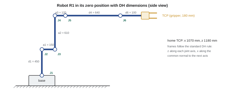
The DH table for R1, built from the dimensions in the figure, is in the program below. The values are illustrative of robots of this class rather than any one model. The second joint has an offset of −90° so that the upper arm points straight up when its joint reads zero, which matches how robot makers usually define the zero position. The gripper's TCP is 180 mm beyond the flange along the flange's z axis.
# Forward kinematics of robot R1 with Denavit-Hartenberg (DH) parameters
import math
def dh(theta, d, a, alpha):
    ct, st, ca, sa = math.cos(theta), math.sin(theta), math.cos(alpha), math.sin(alpha)
    return [[ct, -st * ca, st * sa, a * ct], [st, ct * ca, -ct * sa, a * st], [0, sa, ca, d], [0, 0, 0, 1]]
def mul(A, B):
    return [[sum(A[i][k] * B[k][j] for k in range(4)) for j in range(4)] for i in range(4)]

# Standard DH table for a typical six-axis industrial arm (illustrative dimensions, metres and radians)
#        d       a       alpha        joint offset
DH = [(0.450, 0.150, -math.pi / 2, 0.0),
      (0.000, 0.610,  0.0,         -math.pi / 2),
      (0.000, 0.120, -math.pi / 2, 0.0),
      (0.640, 0.000,  math.pi / 2, 0.0),
      (0.000, 0.000, -math.pi / 2, 0.0),
      (0.100, 0.000,  0.0,         0.0)]
tool = [[1, 0, 0, 0], [0, 1, 0, 0], [0, 0, 1, 0.180], [0, 0, 0, 1]]   # gripper TCP 180 mm along flange z

def fk(q_deg, with_tool=True):
    T = [[1, 0, 0, 0], [0, 1, 0, 0], [0, 0, 1, 0], [0, 0, 0, 1]]
    for (d, a, al, off), q in zip(DH, q_deg):
        T = mul(T, dh(math.radians(q) + off, d, a, al))
    return mul(T, tool) if with_tool else T

c = lambda v: f"{round(v, 3) + 0.0:+.3f}".replace('-0.000', '+0.000')

def show(name, q):
    T = fk(q)
    x, y, z = (T[i][3] * 1000 for i in range(3))
    print(f"{name:26s} q = {q}  ->  TCP x {x:7.1f}  y {y:7.1f}  z {z:7.1f} mm, tool z-axis ({c(T[0][2])}, {c(T[1][2])}, {c(T[2][2])})")
    return T

show("home (all joints zero)", [0, 0, 0, 0, 0, 0])
show("over the infeed pallet", [35, 20, 10, 0, 60, 35])
show("at the balancing arbor", [-50, 35, -5, 0, 60, -50])
T = fk([35, 20, 10, 0, 60, 35]); R = [row[:3] for row in T[:3]]
ortho = max(abs(sum(R[k][i] * R[k][j] for k in range(3)) - (1 if i == j else 0)) for i in range(3) for j in range(3))
print(f"Check: rotation part is orthonormal to within {ortho:.1e}")
# Sensitivity: a 0.01 degree error in joint 2 moves the TCP by about
T1, T2 = fk([35, 20, 10, 0, 60, 35]), fk([35, 20.01, 10, 0, 60, 35])
print(f"0.01 degree in joint 2 moves the TCP {1000*math.dist([T1[i][3] for i in range(3)], [T2[i][3] for i in range(3)]):.3f} mm")home (all joints zero) q = [0, 0, 0, 0, 0, 0] -> TCP x 1070.0 y 0.0 z 1180.0 mm, tool z-axis (+1.000, +0.000, +0.000) over the infeed pallet q = [35, 20, 10, 0, 60, 35] -> TCP x 796.9 y 558.0 z 527.1 mm, tool z-axis (+0.000, +0.000, -1.000) at the balancing arbor q = [-50, 35, -5, 0, 60, -50] -> TCP x 716.2 y -853.5 z 453.6 mm, tool z-axis (+0.000, +0.000, -1.000) Check: rotation part is orthonormal to within 4.4e-16 0.01 degree in joint 2 moves the TCP 0.144 mm
Checking the result
Forward kinematics is easy to program and easy to get wrong, so every implementation needs checks. The first is the zero position, where the answer can be read from the drawing: with all joints at zero, the TCP should lie straight out along x at \(a_1 + d_4 + d_6 + 180 = 1{,}070\) mm and at a height of \(d_1 + a_2 + a_3 = 1{,}180\) mm. The program agrees, and it shows the tool's z axis pointing along +x, horizontally forward. The second is that the rotation part remains orthonormal after six multiplications; it does, to 4 × 10⁻¹⁶, which is rounding. The third check is against the robot itself: jog it to a set of joint angles and compare the TCP position its controller reports, or better, the position measured with a laser tracker, with the calculation.
The two working poses show something useful. Over the infeed pallet, with joints (35°, 20°, 10°, 0°, 60°, 35°), the TCP is at (796.9, 558.0, 527.1) mm and the tool points straight down. At the balancing arbor, with joint 1 at −50°, the TCP is at (716.2, −853.5, 453.6) mm, again pointing down. In both, the wrist angle of 60° plus the shoulder and elbow angles of 30° total 90°, which tilts the tool vertical: a pattern worth recognizing when reading robot programs. The final lines show how a tiny joint error grows at the tool: 0.01° at joint 2, a hundredth of a degree, moves the TCP 0.144 mm, because the error is multiplied by the distance from the joint to the tool, nearly 0.83 m here.
Accuracy and repeatability
That last result explains a distinction every robot user must understand. Repeatability is how closely a robot returns to a position it has been taught; for robots of R1's class it is typically a few hundredths of a millimetre, which is why Owen's error budget in Lesson 1 used 0.06 mm. Absolute accuracy is how closely the robot reaches a position computed from its kinematic model, and it is much worse, often a millimetre or more for an uncalibrated robot. The difference comes from the model: real link lengths and joint offsets differ slightly from the nominal DH values, gears have backlash and the arm bends under its own weight and payload. Taught positions, recorded by jogging the robot to the real location, are therefore repeatable; positions calculated offline from a CAD model may not be accurate enough without calibration. Robot makers offer calibrated, high-accuracy versions for applications such as machining and offline programming, and integrators teach critical positions on site. For BC-1, Simone's team will teach the arbor and drill positions and use calculated positions only for clearance moves.
Worked problem
Where is the gripper at the outfeed?
R1's outfeed place position uses joints (80°, 15°, 15°, 0°, 60°, 80°). Using the pattern above, estimate where the tool points, and then use the program to find the TCP.
Show solution
- Joints 2, 3 and 5 total 90°, so the tool points straight down, as at the pallet.
- Changing the joint list in the program to [80, 15, 15, 0, 60, 80] gives the TCP at (160.1, 908.1, 543.1) mm.
- Its horizontal distance from the base axis is 922.1 mm, 51 mm less than at the pallet, because the shoulder leans forward less; its bearing is exactly 80°, set by joint 1 alone.
Answer: The tool points straight down at (160.1, 908.1, 543.1) mm, 80° around from the base x axis.
Frames in a cell
A cell uses more frames than the robot's own. The world frame is fixed in the cell, often at a corner of the base plate. Each fixture, such as the balancing arbor or the infeed pallet, has a user frame (called a work object or base frame by different makers) defined by touching three points on it with the tool. Robot programs then record positions relative to those frames. When the balancing machine is moved 20 mm after a floor repair, only its user frame needs to be re-taught, and every position defined in it moves with it. Tool frames, defined by touching a fixed point from several orientations, let the robot know where its TCP is. Errors in tool frame definition are among the most common causes of a robot that rotates around the wrong point when jogged in tool coordinates.
Common mistakes
MistakeMixing standard and modified DH conventions in one table.
InsteadState the convention and check the zero position against the drawing.
MistakeForgetting the joint offsets that define the robot's zero position.
InsteadInclude the maker's zero offsets, such as the −90° on joint 2.
MistakeTreating repeatability as accuracy.
InsteadTeach critical positions on the real robot or calibrate it; computed positions can be off by a millimetre or more.
MistakeDefining every position in the robot's base frame.
InsteadUse user frames for fixtures so a moved fixture needs only its frame re-taught.
MistakeComparing orientation angles between robot brands without checking conventions.
InsteadConvert through the rotation matrix, which is unambiguous.
Summary and key terms
- A pose is a position and orientation, described by a frame; homogeneous transforms combine both in a 4 × 4 matrix.
- Transforms chain by multiplication, so forward kinematics is the product of the link transforms and the tool transform.
- DH parameters describe each link with θ, d, a and α; conventions differ, so check the zero position.
- R1's zero-position TCP is at x 1,070 mm, z 1,180 mm, matching the drawing.
- A 0.01° error at joint 2 moves R1's TCP 0.144 mm, showing why accuracy is worse than repeatability.
- Cells use world, user and tool frames so positions survive fixture moves and tool changes.
- Forward kinematics
- Computing the tool pose from the joint positions.
- Frame
- An origin and three perpendicular axes used to describe position and orientation.
- Tool centre point
- The working point of the tool, at the origin of the tool frame.
- Rotation matrix
- An orthonormal 3 × 3 matrix whose columns are a frame's axes.
- Homogeneous transform
- A 4 × 4 matrix combining rotation and translation.
- DH parameters
- Four numbers per link (θ, d, a, α) describing a serial robot's geometry.
- Repeatability
- How closely a robot returns to a taught position.
- Absolute accuracy
- How closely a robot reaches a position computed from its model.
- User frame
- A frame attached to a fixture, used to define positions relative to it.
- Quaternion
- A four-number representation of orientation without the singularities of Euler angles.
Practice problems
Work each problem on paper first, then reveal the answer to check.
Why is the transpose of a rotation matrix its inverse?
Show answer
Its columns are orthonormal unit vectors, so R transposed times R is the identity.
A planar two-link arm has links of 0.5 m and 0.4 m. Where is its tip at joint angles 30° and 60°?
Show answer
x = 0.5 cos 30° + 0.4 cos 90° = 0.433 m; y = 0.5 sin 30° + 0.4 sin 90° = 0.650 m.
A 0.02° error at a joint 1.2 m from the tool moves the tool by about how much?
Show answer
1.2 × 0.02 × π/180 = 0.42 mm.
Why are BC-1's arbor and drill positions taught rather than computed from CAD?
Show answer
Taught positions rely on repeatability, which is far better than the robot's absolute accuracy.
What is the first check of a new forward kinematics program?
Show answer
The zero position, where the TCP can be found directly from the drawing.
Lesson quiz · 5 questions
Score 60% or more to complete this lesson.
Create a free account to save your progress, take quizzes and earn a certificate.