
MEC-460 · Lesson 3 of 12 · 21 min
Drives and power electronics for motion
A motor is only half of an actuator. Between the plant's electrical supply and the motor's windings sits a drive: power electronics that convert a fixed voltage into whatever voltage and current the motor needs at each instant, and control electronics that decide what that should be. In cell BC-1 there are three kinds. A small H-bridge drives the 24 V brushed gearmotor that raises and lowers the stop on the infeed conveyor. Servo drives power axis X1, the drill spindle feed and, inside the robot controllers, every joint of R1 and R2. Variable frequency drives run the conveyor motors. Owen does not need to design power electronics, but he must read the integrator's drive specifications, understand what can go wrong, and recognize when a requirement such as a stopping time depends on a drive setting nobody has written down.
Switching instead of throttling
The simplest way to control a DC motor's speed would be a variable resistor in series with it, but a resistor wastes as heat everything it does not pass to the motor. Power electronics instead switch the supply fully on and fully off thousands of times a second. A transistor that is fully on has a small voltage across it; one that is fully off carries almost no current; in neither state does it dissipate much power. The fraction of each period the switch is on, called the duty cycle D, sets the average voltage: \(V_{avg} = D V_s\). The motor's inductance smooths the current, so the motor responds to the average while the switches stay efficient. This technique, pulse width modulation or PWM, is the basis of every drive in the cell.
The switching frequency is a compromise. Higher frequency means smaller current ripple and quieter operation, since frequencies above about 18 to 20 kHz are inaudible, but each switching transition costs energy, so losses rise with frequency. Drives for small motors commonly switch at 8 to 20 kHz; large drives switch more slowly to keep losses manageable.
The H-bridge
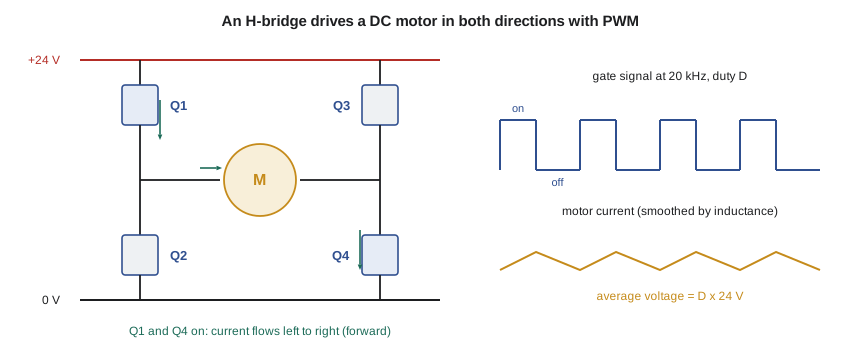
To run a DC motor in both directions, four switches are arranged in an H with the motor as the crossbar. Turning on the top-left and bottom-right switches drives current one way; the other diagonal pair drives it the other way. Turning on both switches on the same side at once would short the supply, a fault called shoot-through, and drive circuits insert a short dead time between turning one switch off and its partner on to prevent it. Turning on both bottom switches shorts the motor's terminals together, which brakes it dynamically using its own back emf. Small H-bridges for 24 V motors come as single integrated circuits; larger ones use discrete MOSFETs with gate drivers.
For the conveyor stop motor, the required duty cycle at each speed follows from the motor equation of Lesson 2: the average voltage must supply the resistive drop plus the back emf, \(D V_s = I R + k_e \omega\). At 2.0 A of load current the motor needs 42.8 percent duty at 1,500 rpm and 72.2 percent at 3,000 rpm, and cannot reach 4,500 rpm at all on 24 V, because that would need more than 100 percent. The program below works through those numbers and the losses in the bridge.
# Drives for the cell: a PWM H-bridge for the conveyor stop motor, regeneration on axis X1, and a conveyor VFD
import math

# 1. 24 V brushed DC gearmotor on the conveyor stop, driven by a MOSFET H-bridge at 20 kHz
Vs, R, kE = 24.0, 1.6, 0.045        # supply (V), armature resistance (ohm), back-emf constant (V per rad/s)
L = 0.8e-3                           # armature inductance (H)
f_pwm = 20e3
for w_rpm in (1500, 3000, 4500):
    w = w_rpm * 2 * math.pi / 60
    I = 2.0                          # load current (A) at the stop's working torque
    D = (I * R + kE * w) / Vs        # duty cycle: average voltage = I R + back emf
    print(f"  {w_rpm:4d} rpm at {I:.1f} A: duty {100*D:5.1f} %" + ("  (not reachable: above 100 %)" if D > 1 else ""))
D = 0.5
ripple = Vs * D * (1 - D) / (L * f_pwm)      # peak-to-peak ripple for a two-quadrant chopper at duty D
print(f"Current ripple at 50 % duty and 20 kHz: {ripple:.2f} A peak to peak")

# MOSFET losses in the two conducting switches
Rds, I, tr_tf = 0.015, 2.0, 60e-9
P_cond = 2 * I**2 * Rds
P_sw = 0.5 * Vs * I * tr_tf * 2 * f_pwm * 2    # two switches, turn-on and turn-off each period
print(f"H-bridge losses: conduction {P_cond:.3f} W, switching {P_sw:.3f} W")

# 2. Axis X1 decelerating: kinetic energy returns to the servo drive's DC bus
J_total = 3.11e-4 + 1.2e-4          # external + M750 rotor (kg m^2), from lesson 2
w = 2250 * 2 * math.pi / 60
E = 0.5 * J_total * w**2
C_bus, V_bus, V_trip = 1.0e-3, 325.0, 390.0   # drive bus capacitance (F), normal and braking-chopper voltages
E_absorb = 0.5 * C_bus * (V_trip**2 - V_bus**2)
print(f"Axis kinetic energy at full speed {E:.1f} J; bus capacitors can absorb {E_absorb:.1f} J before the chopper")
P_avg = E * 0.5 / 2.0                         # about half returns (losses take the rest), once per 2 s cycle
print(f"Average braking power if the chopper did act: {P_avg:.2f} W")

# 3. Conveyor induction motor on a VFD with constant volts per hertz
V_rated, f_rated, poles, slip = 230.0, 60.0, 4, 0.04
for f in (60, 45, 30, 15):
    V = V_rated * f / f_rated
    n = 120 * f / poles * (1 - slip)
print(f" VFD {f:2d} Hz: output {V:5.1f} V, motor about {n:5.0f} rpm")1500 rpm at 2.0 A: duty 42.8 % 3000 rpm at 2.0 A: duty 72.2 % 4500 rpm at 2.0 A: duty 101.7 % (not reachable: above 100 %) Current ripple at 50 % duty and 20 kHz: 0.38 A peak to peak H-bridge losses: conduction 0.120 W, switching 0.115 W Axis kinetic energy at full speed 12.0 J; bus capacitors can absorb 23.2 J before the chopper Average braking power if the chopper did act: 2.99 W VFD 60 Hz: output 230.0 V, motor about 1728 rpm VFD 45 Hz: output 172.5 V, motor about 1296 rpm VFD 30 Hz: output 115.0 V, motor about 864 rpm VFD 15 Hz: output 57.5 V, motor about 432 rpm
The current ripple at 50 percent duty and 20 kHz is 0.38 A peak to peak, about a fifth of the load current, which is acceptable. The losses in the two conducting MOSFETs are about 0.12 W by conduction and 0.12 W by switching, so the bridge barely warms. That is the attraction of switching electronics: the stop motor draws about 50 W, and the drive wastes well under 1 percent.
Servo drives
An industrial servo drive is a three-phase version of the same idea. Its input stage rectifies the incoming AC supply to a DC bus of a few hundred volts, stored in capacitors. Its output stage, an inverter of six transistors, usually insulated-gate bipolar transistors (IGBTs) or MOSFETs in smaller units, synthesizes three sinusoidal phase currents by PWM. The drive's processor reads the motor's encoder to know the rotor angle, measures the phase currents, and controls them so that the stator's field always leads the rotor magnets by the angle that produces torque most efficiently. That inner current loop, which runs at several kilohertz or more, makes the motor a torque source. Around it the drive closes velocity and position loops, which Lesson 10 discusses, and it communicates with the PLC or motion controller over a fieldbus.
Drives also carry protective functions that matter to the cell's design: current limits that cap torque, following-error limits that fault the axis if it lags its command, thermal models of the motor that track its heating, and safety functions. Many modern drives include safe torque off (STO), a hardware input that removes the gate signals from the output transistors so the motor cannot produce torque, implemented to a stated safety integrity. STO is the building block for safe stopping in Lesson 12, but it lets a vertical axis fall and a moving axis coast, which is why the stop category and the brake matter.
Regeneration
When a servo decelerates a load, the motor acts as a generator and pushes energy back into the drive's DC bus. The capacitors absorb it, and their voltage rises. If the energy is more than the capacitors can hold below the drive's overvoltage limit, a braking chopper switches a resistor across the bus to burn off the excess; without one, the drive trips on overvoltage. For axis X1 at full speed the kinetic energy of the motor and reflected load is 12.0 J, and the bus capacitors can absorb 23.2 J between their normal voltage of 325 V and the chopper's threshold of 390 V. No braking resistor is needed, though one costs little and many integrators fit it anyway. For a large robot or a vertical axis lowering a load, regeneration is significant, and drives on a shared DC bus can pass regenerated energy to other axes that are accelerating, which saves both the resistor and the energy.
Worked problem
A heavier fixture
Lucie asks whether X1 could carry a fixture for the larger VT-12 impeller, raising the moving mass from 20 kg to 60 kg. With the same screw and motor, how much kinetic energy must the drive absorb when the axis stops from 0.75 m/s?
Show solution
- Reflected load inertia rises three times, from 2.03 × 10⁻⁴ to 6.08 × 10⁻⁴ kg·m².
- Total inertia: screw 0.99 × 10⁻⁴ + coupling 0.10 × 10⁻⁴ + load 6.08 × 10⁻⁴ + motor 1.20 × 10⁻⁴ = 8.37 × 10⁻⁴ kg·m².
- At 2,250 rpm (235.6 rad/s): \(E = \tfrac{1}{2} J \omega^2 = 23.2\) J.
Answer: About 23 J, right at the bus capacitors' limit, so a braking resistor becomes necessary. The inertia ratio would also rise to about 6:1, still workable for the 750 W motor.
Variable frequency drives for induction motors
A variable frequency drive (VFD) runs an induction motor at adjustable speed by supplying it with a variable frequency. The motor's synchronous speed is \(120 f / p\) rpm for a supply of frequency f and p poles, and the rotor runs a few percent slower because of slip. To keep the magnetic flux constant, and so the available torque, the drive reduces the voltage in proportion to frequency, a scheme called constant volts per hertz. For the cell's 4-pole, 230 V conveyor motors, the program shows the voltage the drive applies and the approximate speed from 60 Hz down to 15 Hz. At low frequency the stator's resistance becomes significant and simple volts-per-hertz control loses torque, so drives add a voltage boost or use vector control, which models the motor and controls its flux and torque directly, much as a servo drive does.
In North America the supply frequency is 60 Hz in both countries, but plant voltages differ: Tidewater's main distribution is 600 V three-phase, stepped down for small loads. The drives' input voltage, short-circuit rating and the motor's insulation, since PWM voltage edges stress windings, must suit the supply, and the panel must follow the Canadian Electrical Code and the CSA standards for industrial machinery and control panels. Long cables between a VFD and its motor can create voltage reflections that double the peak voltage at the motor terminals; output filters or motors rated for inverter duty prevent insulation damage.
Electromagnetic compatibility
Fast-switching drives are electrically noisy. Each switching edge produces high-frequency currents that flow through motor cable capacitance to ground and back, and they can couple into sensor wiring, encoder signals and network cables. A pressure transducer reading that jumps whenever the conveyor starts, or an encoder that drops counts when X1 accelerates, is a classic mechatronics fault with an electrical cause. The defences are well established: shielded motor cables with the shield bonded at both ends with low-impedance clamps, sensor and power cables run in separate trays and crossed at right angles, a single well-planned ground system, and line filters at the drive input. Owen adds a line to the requirements asking Baywind to state how the panel and cabling follow the drive manufacturers' installation guidance, since that guidance is usually what makes the drives' emission and immunity claims valid.
Common mistakes
MistakeTurning on both switches in one leg of an H-bridge.
InsteadThat shorts the supply; drivers insert dead time to prevent shoot-through.
MistakeAssuming safe torque off holds a vertical axis.
InsteadSTO removes torque; a brake, or a different stop category, is needed to hold a load.
MistakeIgnoring regenerated energy when sizing a drive.
InsteadCompare the kinetic energy at stop with what the bus capacitors can absorb, and fit a braking resistor if needed.
MistakeUsing constant volts per hertz down to very low speed without boost.
InsteadAdd voltage boost or use vector control to keep torque at low frequency.
MistakeRunning sensor cables next to motor cables.
InsteadSeparate them, shield and bond properly, and follow the drive maker's installation guidance.
Summary and key terms
- Drives switch transistors fully on and off; the duty cycle sets average voltage and losses stay small.
- An H-bridge drives a DC motor both ways; dead time prevents shoot-through.
- The conveyor-stop motor needs 42.8 % duty at 1,500 rpm and cannot reach 4,500 rpm on 24 V.
- Servo drives control phase currents from encoder feedback and provide limits and safe torque off.
- Decelerating X1 returns 12.0 J, within the 23.2 J its bus capacitors can absorb.
- VFDs vary frequency with voltage in proportion; good cabling practice keeps drive noise out of signals.
- Pulse width modulation
- Controlling average voltage by switching fully on and off with a variable duty cycle.
- Duty cycle
- The fraction of each switching period that a switch is on.
- H-bridge
- Four switches arranged so a DC motor can be driven in either direction.
- Shoot-through
- Both switches in one leg conducting at once, shorting the supply.
- DC bus
- The rectified, capacitor-smoothed DC supply inside a drive.
- Regeneration
- Energy returned from a decelerating motor to the drive.
- Braking chopper
- A switch and resistor that dissipate excess regenerated energy.
- Safe torque off
- A safety function that removes a drive's ability to produce motor torque.
- Volts per hertz
- Induction motor control keeping voltage proportional to frequency.
- Vector control
- Drive control that models a motor to command flux and torque separately.
Practice problems
Work each problem on paper first, then reveal the answer to check.
A 48 V H-bridge runs at 35 % duty. What average voltage does the motor see?
Show answer
0.35 × 48 = 16.8 V.
Why is switching at 20 kHz common for small drives?
Show answer
It is above the audible range and keeps ripple small, while switching losses remain modest.
A 4-pole induction motor runs on a VFD at 40 Hz with 3 % slip. What is its speed?
Show answer
120 × 40/4 × 0.97 = 1,164 rpm.
What two things happen if an axis regenerates more energy than its drive can absorb, with no braking resistor?
Show answer
The bus voltage rises and the drive trips on overvoltage, leaving the axis without controlled deceleration.
Give two measures that stop drive noise from corrupting a transducer signal.
Show answer
Separate and cross cables at right angles, and use shielded motor cable bonded at both ends, among others.
Lesson quiz · 5 questions
Score 60% or more to complete this lesson.
Create a free account to save your progress, take quizzes and earn a certificate.