
MEC-460 · Lesson 4 of 12 · 21 min
Pneumatic and hydraulic actuators in automation
Walk through any assembly plant and the soft hiss of compressed air is everywhere. Pneumatic cylinders clamp parts, lift pallets, push rejects off conveyors and open grippers, because they are cheap, fast, tolerant of stalls and overloads, and easy to understand. Cell BC-1 has a dozen of them: the clamp that holds an impeller at the drill station, the lifter that raises pallets off the infeed conveyor, the door on the balancing machine, the jaws of R1's gripper and R2's vacuum cup. Hydraulics, which use oil at far higher pressure, appear where large forces are needed in a compact space, such as a press. This lesson covers how to size these actuators, how their valves and circuits work, and what they cost to run.
Pneumatic cylinders
A cylinder converts air pressure into force on a piston. The force on extension is the gauge pressure times the piston area; on retraction the rod occupies part of the area, so the force is smaller:
where D is the bore, d the rod diameter and \(\eta\) an allowance, typically 0.8 to 0.9, for seal friction and the pressure drop between the regulator and the cylinder. Plant air is usually distributed at 6 to 7 bar gauge and regulated at each machine. Designers take the lower of the regulated pressure and the pressure that can be relied on when the compressors are working hardest, because a clamp that holds at 6 bar but slips at 5 is a hidden failure waiting for a busy afternoon.
Cylinders come in standard bores, commonly 32, 40, 50, 63, 80 and 100 mm in the ISO 15552 series, with matching rods. Double-acting cylinders use air to move both ways; single-acting ones use air one way and a spring to return. Guided cylinders add bearings and rods to resist side loads, which plain cylinders handle poorly. End-of-stroke cushions slow the piston in its last few millimetres; without them, or with them badly adjusted, a fast cylinder hammers its end caps and the structure it is bolted to.
Sizing the drill-station clamp
Baywind's drawing shows a clamp that presses the impeller's hub against a locating face while the drill removes metal from the shroud. The drilling thrust and the torque reaction at the locating face need a holding force of 900 N, and Owen asks for a factor of 1.5 on top of it, since a part that shifts during drilling ruins the correction. The program below computes the force available from three bores at 6 bar with an 85 percent efficiency allowance. The 40 and 50 mm cylinders fall short; the 63 mm cylinder gives 1,590 N on extension, enough with the margin. Both directions matter in some designs; here only extension clamps.
# Pneumatics in cell BC-1: the impeller clamp cylinder, the gripper, air use and cost
import math
p_gauge = 6.0e5         # supply pressure at the valve, Pa gauge (6 bar)
p_atm = 1.013e5
eff = 0.85              # allowance for seal friction and pressure drop

# Clamp cylinder on the drill station: must hold 900 N against the drilling thrust and torque reaction
need = 900.0
for bore in (40, 50, 63):
    rod = {40: 16, 50: 20, 63: 20}[bore]
    A_ext = math.pi * (bore / 1000)**2 / 4
    A_ret = A_ext - math.pi * (rod / 1000)**2 / 4
    F_ext, F_ret = p_gauge * A_ext * eff, p_gauge * A_ret * eff
    print(f"  bore {bore} mm: extend {F_ext:6.0f} N, retract {F_ret:6.0f} N  ->  {'enough' if F_ext >= 1.5 * need else 'too small'} for 1.5 x {need:.0f} N")

# Air consumption of the chosen 63 mm cylinder: 25 mm stroke, one double stroke per impeller
bore, rod, stroke = 0.063, 0.020, 0.025
V_ext = math.pi * bore**2 / 4 * stroke
V_ret = (math.pi * bore**2 / 4 - math.pi * rod**2 / 4) * stroke
ratio = (p_gauge + p_atm) / p_atm
free_air = (V_ext + V_ret) * ratio * 1000          # litres of free air per double stroke
tube = math.pi * 0.006**2 / 4 * 2.0 * 2 * ratio * 1000   # two 2 m lengths of 6 mm bore tube filled each cycle
per_cycle = free_air + tube
cycles_per_h = 3600 / 79.5
print(f"Free air per clamp cycle: cylinder {free_air:.2f} L + tubing {tube:.2f} L = {per_cycle:.2f} L")

# Gripper on robot R1 (double-acting parallel gripper, 2 jaws, 40 mm bore each side)
grip_cycle = 0.85                                   # litres of free air per open-close, from the catalogue
moves = 6                                            # grips per impeller
total_L_per_h = (per_cycle + grip_cycle * moves) * cycles_per_h
print(f"Cell air use: {total_L_per_h/60:.1f} L/min of free air on average")
kWh_per_m3 = 0.12                                    # compressor energy per cubic metre of free air (typical)
hours = 16 * 250
cost_rate = 0.14                                    # electricity, per kWh
annual = total_L_per_h / 1000 * hours * kWh_per_m3 * cost_rate
print(f"Compressed air energy about {total_L_per_h/1000*hours*kWh_per_m3:.0f} kWh a year, cost about {annual:.0f} dollars a year")
print(f"A single 1 mm leak at 6 bar (about 1.1 L/s of free air) wastes about {1.1*3600/1000*hours*kWh_per_m3:.0f} kWh a year")

# Hydraulic press for seating seal sleeves: force from a 40 mm cylinder at 100 bar
A = math.pi * 0.040**2 / 4
print(f"Hydraulic 40 mm cylinder at 100 bar: {100e5 * A / 1000:.1f} kN; the same bore on 6 bar air: {6e5 * A / 1000:.2f} kN")bore 40 mm: extend 641 N, retract 538 N -> too small for 1.5 x 900 N bore 50 mm: extend 1001 N, retract 841 N -> too small for 1.5 x 900 N bore 63 mm: extend 1590 N, retract 1430 N -> enough for 1.5 x 900 N Free air per clamp cycle: cylinder 1.02 L + tubing 0.78 L = 1.81 L Cell air use: 5.2 L/min of free air on average Compressed air energy about 150 kWh a year, cost about 21 dollars a year A single 1 mm leak at 6 bar (about 1.1 L/s of free air) wastes about 1901 kWh a year Hydraulic 40 mm cylinder at 100 bar: 12.6 kN; the same bore on 6 bar air: 0.75 kN
Valves and circuits
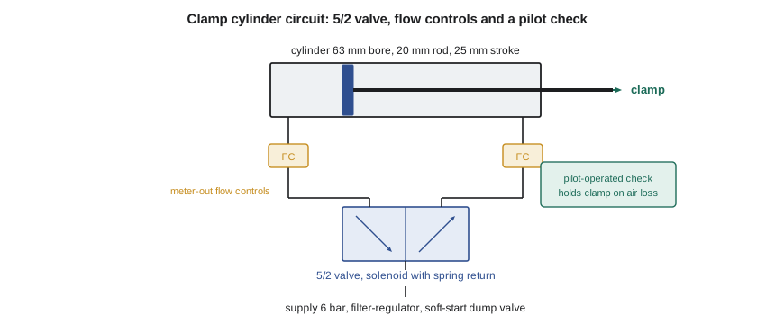
A directional control valve routes air to the cylinder. It is named by its ports and positions: a 5/2 valve has five ports (supply, two outputs to the cylinder and two exhausts) and two positions. It may be shifted by a solenoid and returned by a spring, so it fails to a known state when power is lost, or held by two solenoids so it stays where it was. That choice is a safety decision, not a detail: for the clamp, a spring-return valve would release the impeller if the control power failed, so Baywind chose a design in which loss of power leaves the clamp closed until a deliberate release. Valves for a whole machine are usually grouped on a valve island, a manifold with a network connection to the PLC, which saves wiring.
Speed is set with flow controls, small adjustable restrictors with a bypass check valve. Restricting the air leaving the cylinder, called meter-out control, gives smoother motion than restricting the air entering it, because the piston is then held between two cushions of air. A pilot-operated check valve on the clamping side traps the air in the cylinder if the supply is lost, so the clamp keeps its grip. At the machine's air inlet, a filter-regulator removes water and dirt and sets the pressure, and a soft-start dump valve does two jobs: it brings pressure up slowly on start-up, so cylinders do not slam into position, and it exhausts the machine's air when the safety system demands, removing stored energy before anyone reaches in. Lesson 12 returns to that function.
Air consumption and its cost
Compressed air is often called the most expensive utility in a plant, and the reason is easy to see. A compressor takes in air at atmospheric pressure and compresses it, losing most of the input energy as heat. Typical industrial systems use roughly 0.1 to 0.15 kWh of electricity per cubic metre of free air delivered at 7 bar, before any leaks. Consumption is computed in free air, that is, air measured at atmospheric pressure. A cylinder of swept volume V working at gauge pressure p uses \(V (p + p_{atm})/p_{atm}\) of free air per stroke, and the tubing between valve and cylinder is filled and dumped every cycle too.
The program shows that one clamp cycle uses 1.02 L of free air in the cylinder and 0.78 L in two 2 m lengths of 6 mm tubing, nearly as much again. Mounting the valve close to the cylinder would halve the tube volume. With R1's gripper opening and closing six times per impeller, the cell's working consumption averages 5.2 L/min, about 150 kWh a year on two shifts, which costs about 21 dollars. That is negligible. The last line is not: a single leak through a 1 mm hole at 6 bar wastes roughly 1.1 L/s, around 1,900 kWh a year, which is ten times the cell's useful consumption. Leaks of that size are common in plants without a leak programme and are found by listening on quiet weekends or with an ultrasonic detector.
Worked problem
A pallet lifter
The infeed pallet lifter raises a 14 kg pallet and impeller 40 mm. It uses a guided double-acting cylinder of 32 mm bore and 12 mm rod at 6 bar. Check the lifting force with an 85 % allowance and a factor of 2 for acceleration and friction in the guides, and find its free-air use per double stroke.
Show solution
- Extension force: \(6 × 10^5 × \pi × 0.032^2/4 × 0.85 = 410\) N.
- Required: 14 × 9.81 × 2 = 275 N, so the force is adequate.
- Swept volumes: extend 3.22 × 10⁻⁵ m³, retract 2.77 × 10⁻⁵ m³; total 6.0 × 10⁻⁵ m³.
- Free air per double stroke: 6.0 × 10⁻⁵ × (7.013/1.013) = 4.1 × 10⁻⁴ m³ = 0.41 L.
Answer: The 32 mm cylinder lifts the pallet with margin and uses about 0.41 L of free air per cycle, plus its tubing.
Positioning with air
A plain pneumatic cylinder has two stable positions, the ends of its stroke. Intermediate positions can be reached with mechanical stops, multi-position cylinders, or proportional valves with position feedback, but air is compressible, so a pneumatic axis is soft and difficult to control precisely against varying loads. For that reason the drill station's positioning along the shroud uses the servo axis X1, while air does the clamping, which needs force rather than position. The rule of thumb in automation is to use pneumatics for end-to-end motion and holding, and electric axes when the position, speed profile or force must be programmable. Electric cylinders, a servo motor driving a screw in a cylinder-shaped housing, now compete with pneumatics in many applications because they avoid the energy cost of compressed air and give full control of position and force, at a higher purchase price.
Hydraulics
Hydraulic systems use oil at pressures typically between 70 and 350 bar, more than ten to fifty times plant air pressure. Force is again pressure times area, so a 40 mm bore at 100 bar gives 12.6 kN, against 0.75 kN for the same cylinder on 6 bar air. Oil is nearly incompressible, so hydraulic axes are stiff and, with servo or proportional valves, can be positioned precisely under heavy load, which is why presses, injection moulding machines and heavy mobile equipment use them. The costs are a power unit with pump, reservoir, filtration and cooling, the risk of leaks onto floors and parts, and a serious hazard from stored energy and high-pressure fluid injection injuries. Tidewater's seal sleeve press at the manual bench is hydraulic, but in BC-1 the forces are small enough for air and electric actuators, which keeps oil out of a cell that handles clean seal faces.
Stored energy
Pneumatic and hydraulic systems store energy in compressed fluid even when the machine is stopped. A cylinder trapped by a pilot-operated check valve, which is exactly what holds the clamp closed on power loss, will move if its fitting is loosened. Accumulators in hydraulic systems hold large amounts of energy. Safe maintenance therefore requires isolating and releasing stored fluid energy, not only switching off electricity, and the lockout procedures required by CSA Z460, the Canadian standard for control of hazardous energy cover pneumatic and hydraulic energy explicitly. Owen adds two requirements: every pneumatic circuit that can trap pressure shall have a means to release it, with a gauge showing it has been released, and the cell's lockout procedure shall list each one.
Common mistakes
MistakeSizing a cylinder at nominal plant pressure with no allowance.
InsteadUse the lowest reliable regulated pressure and an efficiency allowance of about 0.85.
MistakeForgetting that retraction force is smaller.
InsteadSubtract the rod area for the retract stroke.
MistakeUsing a spring-return valve where loss of power would release a clamped part.
InsteadChoose valve types and check valves for the safe state on power and air loss.
MistakeIgnoring tubing volume in air consumption.
InsteadInclude the tubing, and mount valves close to their cylinders.
MistakeLocking out only electrical energy.
InsteadIsolate and release trapped air and hydraulic pressure as well.
Summary and key terms
- Cylinder force is gauge pressure times area times an allowance; retraction force uses the annular area.
- The BC-1 clamp needs 1,350 N with margin; only the 63 mm bore at 6 bar gives enough, 1,590 N.
- Valves are named by ports and positions; their behaviour on power and air loss is a safety decision.
- Meter-out flow controls give smooth motion; soft-start dump valves pressurize gently and exhaust on demand.
- The cell uses about 5.2 L/min of free air; a single 1 mm leak would waste ten times its useful energy.
- Hydraulics give large, stiff forces but bring leaks and stored-energy hazards.
- Double-acting cylinder
- A cylinder driven by air in both directions.
- Free air
- Air volume measured at atmospheric pressure.
- 5/2 valve
- A directional valve with five ports and two switching positions.
- Meter-out control
- Restricting the exhaust air from a cylinder to control its speed.
- Pilot-operated check valve
- A check valve that can be opened by a pilot signal, used to trap air in a cylinder.
- Soft-start dump valve
- An inlet valve that pressurizes a machine slowly and exhausts it on demand.
- Valve island
- A manifold of valves with a shared network connection.
- Cushioning
- Slowing a piston near the end of its stroke to avoid impact.
- Electric cylinder
- A servo-driven screw actuator packaged like a cylinder.
- Stored energy
- Energy remaining in a system after its supply is switched off, such as trapped pressure.
Practice problems
Work each problem on paper first, then reveal the answer to check.
What extension force does a 50 mm bore cylinder give at 5.5 bar with an 0.85 allowance?
Show answer
5.5 × 10⁵ × π × 0.05²/4 × 0.85 = 918 N.
A 40 mm bore, 16 mm rod cylinder at 6 bar: what is its retract force with an 0.85 allowance?
Show answer
6 × 10⁵ × π(0.040² − 0.016²)/4 × 0.85 = 538 N.
How much free air does 0.5 L of swept volume at 6 bar gauge use?
Show answer
0.5 × 7.013/1.013 = 3.46 L.
Why is meter-out flow control preferred for a cylinder's speed?
Show answer
The piston moves between two air cushions, giving smoother, more stable motion.
Give two reasons X1, not a pneumatic cylinder, positions the drill.
Show answer
The positions must be programmable along the shroud, and air's compressibility makes precise positioning under load difficult.
Lesson quiz · 5 questions
Score 60% or more to complete this lesson.
Create a free account to save your progress, take quizzes and earn a certificate.