
MEC-460 · Lesson 2 of 12 · 23 min
Electric motors and actuator sizing
Baywind's first detailed design package covers axis X1, the linear axis that carries the impeller fixture under the drill spindle at the correction station. The drawing shows a ball-screw unit with a 500 mm working stroke, a 20 mm screw and linear guides, and a servo motor coupled directly to the screw. The motor box on the drawing says only 400 W. Owen's task is to check that choice, which means understanding how electric motors produce torque, what limits them, and how the inertia and friction of a mechanism appear at the motor shaft.
How electric motors make torque
Every electric motor in the cell turns current into force through the interaction of a magnetic field and a current-carrying conductor. In a brushed DC motor, permanent magnets in the stator provide the field and a commutator with brushes switches current between windings on the rotor so the torque always acts the same way. Torque is proportional to current, \(T = k_t I\), and the voltage the rotor generates as it spins, the back electromotive force, is proportional to speed, \(E = k_e \omega\). In consistent SI units the two constants are numerically equal. The supply voltage must overcome both the back emf and the resistive drop, \(V = I R + k_e \omega\), so at a fixed voltage the speed falls as load torque rises. Brushed motors are cheap and easy to drive, which is why the conveyor stop in BC-1 uses one, but their brushes wear and spark.
A brushless DC motor, or the closely related permanent magnet synchronous motor used in most industrial servos, moves the magnets to the rotor and the windings to the stator. Electronics replace the commutator: a drive switches current in the stator phases in step with the rotor position, which it reads from a sensor such as an encoder or Hall effect devices. Without brushes the motor is more reliable, can run faster, and dissipates its heat in the stator where it can be conducted away. A servo motor is such a motor packaged with a high-resolution encoder and, often, a holding brake, and sold together with a drive that closes current, velocity and position loops.
A stepper motor has many teeth on its rotor and stator and moves in fixed steps, typically 200 per revolution, as the drive energizes its phases in sequence. Microstepping drives interpolate between steps. Steppers hold position without feedback, which makes them cheap and simple for light, predictable loads such as the press on the seal test fixture. Their weakness is that if the load demands more torque than the motor can supply at that speed, the rotor slips a step and the controller does not know. Their torque also falls steeply with speed. They suit short, light moves; servos suit fast, heavy or critical ones.
The AC induction motor, the workhorse of industry, has no magnets at all. The stator's rotating field induces currents in a squirrel-cage rotor, which turns slightly slower than the field; the difference, called slip, is what induces the current. Induction motors are rugged and cheap and run the conveyors and the balancing machine's spindle. With a variable frequency drive they become adjustable-speed machines, as Lesson 3 shows.
Torque-speed curves and ratings
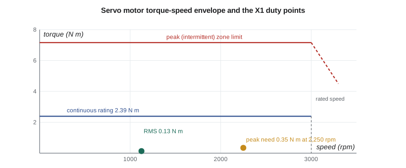
A servo motor's catalogue page is dominated by a torque-speed curve like the one in the figure. Below the continuous line the motor can run indefinitely without overheating, because the heat generated in its windings, which rises with the square of current and therefore of torque, can escape. Above it, up to the peak line, the motor can run only briefly. Speed is limited by the voltage available to overcome back emf, and above the rated speed the available torque falls. A sizing therefore checks three things: the peak torque during acceleration lies inside the intermittent zone at the speed where it occurs, the root mean square torque over the whole cycle lies below the continuous rating, and the maximum speed is within the rated speed.
The root mean square, or RMS, torque is the square root of the time-weighted average of torque squared. It is the right measure of heating because winding loss is proportional to current squared. A motor that accelerates hard for a third of a second, cruises, decelerates and then dwells has an RMS torque much lower than its peak. Designers usually keep at least 20 to 25 percent of margin on both peak and RMS to allow for friction that grows with wear, cable drag, and estimates that prove optimistic.
Reflecting the mechanism to the motor
A ball screw converts rotation to linear motion. A screw with lead \(p\) advances the nut by \(p\) for each revolution, so a linear speed \(v\) requires a motor speed of \(v/p\) revolutions per second. The carriage mass \(m\) appears at the motor shaft as an equivalent inertia
which is the general rule for any transmission: inertia reflected through a ratio is divided by the square of that ratio. The screw itself is a solid steel cylinder whose inertia, \(\pi \rho L d^4/32\), grows with the fourth power of diameter, and a 20 mm screw 800 mm long turns out to contribute almost half as much as the 20 kg carriage. Friction in the linear guides, \(\mu m g\), becomes a torque \(\mu m g p/(2\pi\eta)\), where \(\eta\) is the screw's efficiency, about 0.9 for a ball screw. The torque to accelerate is the total inertia, motor plus everything reflected, times the angular acceleration, divided by efficiency, plus friction. During deceleration the screw drives the motor, and the efficiency works in the opposite sense.
Inertia ratio
Torque and speed are necessary but not sufficient. The ratio of the load inertia reflected to the motor shaft to the motor's own rotor inertia governs how well a servo loop can control the axis. A motor with a small, light rotor driving a large reflected inertia through a slightly springy coupling and screw forms a two-mass system with a resonance that the velocity loop excites; the drive must then be tuned softly, and the axis settles slowly or rings. Servo manufacturers publish recommended ratios, commonly up to about 10:1 for a direct-coupled ball screw and higher for stiff direct-drive mechanisms, with lower ratios for high-performance axes. The exact limit depends on the drive's tuning features and the stiffness of the mechanism, so it is a guideline rather than a law, but a ratio of 25 to 1 on a belt-and-screw axis is a reliable recipe for trouble.
# Sizing the servo motor for linear axis X1: a ball-screw shuttle carrying the impeller fixture
import math
g = 9.81
m = 20.0            # moving mass: carriage 12 kg + fixture 4 kg + impeller 4 kg (kg)
lead = 0.020        # ball-screw lead (m per revolution)
d_s, L_s = 0.020, 0.80   # screw diameter and length (m)
rho = 7850.0
eta = 0.90          # ball-screw efficiency
mu = 0.01           # linear guide friction coefficient
stroke, t_move = 0.50, 1.0    # 500 mm move in 1.0 s with a 1/3-1/3-1/3 trapezoidal profile
t_acc = t_move / 3
v_max = stroke / (t_move - t_acc)         # peak speed of a trapezoid with equal ramps
a = v_max / t_acc
n_max = v_max / lead * 60                 # motor speed with direct coupling (rpm)

J_screw = math.pi * rho * L_s * d_s**4 / 32
J_load = m * (lead / (2 * math.pi))**2    # mass reflected through the screw
J_coup = 1.0e-5
J_motor = 1.2e-5                          # candidate motor rotor inertia (kg m^2)
J_ext = J_screw + J_load + J_coup
ratio = J_ext / J_motor
print(f"Peak speed {v_max:.3f} m/s, acceleration {a:.2f} m/s^2, motor speed {n_max:.0f} rpm")
print(f"Inertias (kg m^2): screw {J_screw:.2e}, load {J_load:.2e}, coupling {J_coup:.1e}; total external {J_ext:.2e}")
print(f"Inertia ratio load : motor = {ratio:.1f} : 1")

T_fric = mu * m * g * lead / (2 * math.pi * eta)
alpha = a / lead * 2 * math.pi
T_acc = (J_ext + J_motor) * alpha / eta + T_fric
T_run = T_fric
T_dec = (J_ext + J_motor) * alpha * eta * -1 + T_fric   # decelerating: screw efficiency works the other way
dwell = 1.0
seg = [(T_acc, t_acc), (T_run, t_move - 2 * t_acc), (T_dec, t_acc), (0.0, dwell)]
T_rms = math.sqrt(sum(T * T * t for T, t in seg) / sum(t for _, t in seg))
print(f"Torque: accelerate {T_acc:.3f} N m, run {T_run:.4f} N m, decelerate {T_dec:.3f} N m")
print(f"RMS torque over a {t_move + dwell:.0f} s cycle: {T_rms:.3f} N m")

motors = [("M200  200 W", 0.64, 1.91, 3000, 1.2e-5), ("M400  400 W", 1.27, 3.82, 3000, 2.6e-5),
          ("M750  750 W", 2.39, 7.16, 3000, 1.2e-4)]
for name, Tc, Tp, nr, Jm in motors:
    r = J_ext / Jm
    Tpk = T_acc - J_motor * alpha / eta + Jm * alpha / eta     # peak torque with this motor's own rotor
    why = []
    if Tc < 1.25 * T_rms: why.append("RMS torque")
    if Tp < 1.25 * Tpk: why.append("peak torque")
    if nr < n_max: why.append("speed")
    if r > 10: why.append("inertia ratio")
    verdict = "suitable" if not why else "fails on " + ", ".join(why)
    print(f"  {name}: rated {Tc} N m, peak {Tp} N m, needs peak {Tpk:.3f} N m, inertia ratio {r:4.1f}  ->  {verdict}")

# Option: a 2:1 timing-belt reduction between motor and screw (motor runs twice as fast)
N = 2.0
J_ext2 = J_ext / N**2 + 0.6e-5                 # reflected screw and load, plus the two pulleys
n2 = n_max * N
print(f"With a 2:1 belt: motor speed {n2:.0f} rpm, M400 inertia ratio {J_ext2 / 2.6e-5:.1f} : 1"
f" -> {'fails on speed' if n2 > 3000 else 'within rating'}")Peak speed 0.750 m/s, acceleration 2.25 m/s^2, motor speed 2250 rpm Inertias (kg m^2): screw 9.86e-05, load 2.03e-04, coupling 1.0e-05; total external 3.11e-04 Inertia ratio load : motor = 25.9 : 1 Torque: accelerate 0.261 N m, run 0.0069 N m, decelerate -0.199 N m RMS torque over a 2 s cycle: 0.134 N m M200 200 W: rated 0.64 N m, peak 1.91 N m, needs peak 0.261 N m, inertia ratio 25.9 -> fails on inertia ratio M400 400 W: rated 1.27 N m, peak 3.82 N m, needs peak 0.272 N m, inertia ratio 12.0 -> fails on inertia ratio M750 750 W: rated 2.39 N m, peak 7.16 N m, needs peak 0.346 N m, inertia ratio 2.6 -> suitable With a 2:1 belt: motor speed 4500 rpm, M400 inertia ratio 3.2 : 1 -> fails on speed
The results surprise Owen. The 500 mm move in one second needs a peak speed of 0.750 m/s, which with a 20 mm lead is 2,250 rpm at the motor, comfortably inside a 3,000 rpm rating. The torques are tiny: 0.261 N·m to accelerate and an RMS of 0.134 N·m over the cycle, a fifth of the smallest motor's continuous rating. On torque alone a 200 W motor would do. But the reflected inertia of the screw and carriage, 3.11 × 10⁻⁴ kg·m², is 26 times the 200 W motor's rotor and 12 times the 400 W motor's. Only the 750 W motor, with a heavier rotor, brings the ratio down to 2.6:1. Baywind's 400 W choice would move the axis, but it would be hard to tune for a crisp, accurate stop at the drill.
The last lines test a common remedy. A 2:1 timing-belt reduction divides the reflected inertia by four and brings the 400 W motor's ratio to 3.2:1, but the motor must then turn at 4,500 rpm, beyond its rating. Another option, not computed here, would be a medium-inertia version of the 400 W motor, which many manufacturers offer for exactly this situation. Owen writes up the finding and Baywind agrees to change to the 750 W motor. The drive and cable change with it, and the extra cost is small against the risk of a poorly behaved axis.
Worked problem
A stepper for the seal press
The seal test fixture uses a stepper motor driving a 5 mm lead screw to press a seal face 12 mm into its holder against a spring force rising to 150 N. The screw efficiency is 0.35 (a plain lead screw), and the stepper's pull-out torque is 0.45 N·m at 600 rpm. Is the motor adequate at 600 rpm?
Show solution
- Speed: 600 rpm × 5 mm = 50 mm/s, so the 12 mm stroke takes 0.24 s.
- Torque to push 150 N: \(T = F p/(2\pi\eta) = 150 × 0.005/(2\pi × 0.35) = 0.341\) N·m.
- Margin: 0.45 / 0.341 = 1.32, which is thin for a stepper, since a missed step goes undetected.
Answer: It is adequate but thin. Slowing to a speed where pull-out torque is higher, or confirming position with a home sensor before each cycle, makes the press dependable.
Gearheads and the optimum ratio
When a load is heavy and slow, such as a turntable or a robot joint, a gearhead between the motor and load trades speed for torque. With ratio N the load torque at the motor is divided by N and the reflected inertia by N². For a pure inertia load there is a ratio that minimizes the motor torque needed to achieve a given load acceleration: the one that makes the reflected load inertia equal to the motor's inertia, \(N = \sqrt{J_L/J_m}\). It is a useful starting point, but in practice the ratio is chosen to keep the motor within its speed rating at the load's top speed, since motor torque at the motor's own optimum ratio is often far from the binding constraint. Robots use high-ratio gears such as strain-wave and cycloidal reducers in their joints, which Lesson 11 returns to.
The motor's thermal and electrical environment
A motor's ratings assume it is mounted on a heat-conducting flange at an ambient temperature, commonly 40 °C. Mounted on a plastic bracket inside a warm enclosure, it will run hotter at the same torque. Altitude, enclosure ratings against dust and coolant, and the duty cycle all matter. On the electrical side, the motor and drive are supplied from the plant's three-phase system, 600 V at Tidewater, through a transformer or a drive suited to it, and the wiring, protection and grounding follow the Canadian Electrical Code and the CSA standards for industrial machinery and control panels. Owen does not design that wiring, but he checks that the integrator's panel drawings show it and that someone qualified has done it.
Common mistakes
MistakeSizing a servo on torque alone.
InsteadCheck peak torque, RMS torque, maximum speed and the inertia ratio.
MistakeUsing peak torque to judge heating.
InsteadHeating follows current squared, so compare RMS torque over the duty cycle with the continuous rating.
MistakeForgetting the screw's own inertia.
InsteadA solid screw's inertia grows with d⁴ and can rival the carriage's.
MistakeAdding a reduction to fix inertia without checking motor speed.
InsteadA ratio N multiplies motor speed by N; confirm it stays within the rating.
MistakeRunning a stepper close to its pull-out torque.
InsteadKeep a generous margin or add position feedback, since missed steps are invisible.
Summary and key terms
- Brushed DC, brushless servo, stepper and induction motors each suit different duties; torque is proportional to current.
- Size a motor for peak torque in the intermittent zone, RMS torque below the continuous rating, and speed within rating.
- Mass on a screw reflects to the motor as m(p/2π)², and any ratio N divides reflected inertia by N².
- The load-to-motor inertia ratio governs how well a servo can be tuned; keep it within the manufacturer's guidance.
- For X1 the torques are small, but the inertia ratio rules out the 200 W and 400 W motors; the 750 W motor gives 2.6:1.
- Steppers need generous torque margins because missed steps are not detected.
- Back emf
- The voltage a motor generates as it turns, proportional to speed.
- Torque constant
- The torque produced per ampere of motor current.
- Servo motor
- A brushless motor with an encoder, run in closed-loop control by a matching drive.
- Stepper motor
- A motor that moves in discrete steps as its phases are energized in sequence.
- RMS torque
- The square root of the time-weighted mean of torque squared over a duty cycle.
- Continuous rating
- The torque a motor can deliver indefinitely without overheating.
- Reflected inertia
- The inertia a load presents at the motor shaft after transmission ratios.
- Inertia ratio
- Reflected load inertia divided by motor rotor inertia.
- Lead
- The linear distance a screw advances its nut per revolution.
- Pull-out torque
- The largest torque a stepper can deliver at a given speed without losing steps.
Practice problems
Work each problem on paper first, then reveal the answer to check.
A 15 kg carriage rides on a screw with 10 mm lead. What inertia does it reflect to the motor?
Show answer
15 × (0.010/2π)² = 3.80 × 10⁻⁵ kg·m².
A motor's torque is 1.0 N·m for 0.2 s, 0.1 N·m for 0.6 s and zero for 0.2 s. What is the RMS torque?
Show answer
√((1.0² × 0.2 + 0.1² × 0.6)/1.0) = 0.453 N·m.
A gearhead of ratio 5 sits between a motor and a load of 0.02 kg·m². What inertia does the motor see from the load?
Show answer
0.02/25 = 8 × 10⁻⁴ kg·m².
Why does X1's inertia ratio, not its torque, decide the motor?
Show answer
The required torques are a small fraction of every candidate's rating, but only the 750 W motor's rotor is heavy enough to keep the ratio within guidance.
What is the optimum gear ratio for a pure inertia load of 0.05 kg·m² on a motor of 2 × 10⁻⁴ kg·m²?
Show answer
√(0.05/0.0002) = 15.8.
Lesson quiz · 5 questions
Score 60% or more to complete this lesson.
Create a free account to save your progress, take quizzes and earn a certificate.